Mechanical Construction

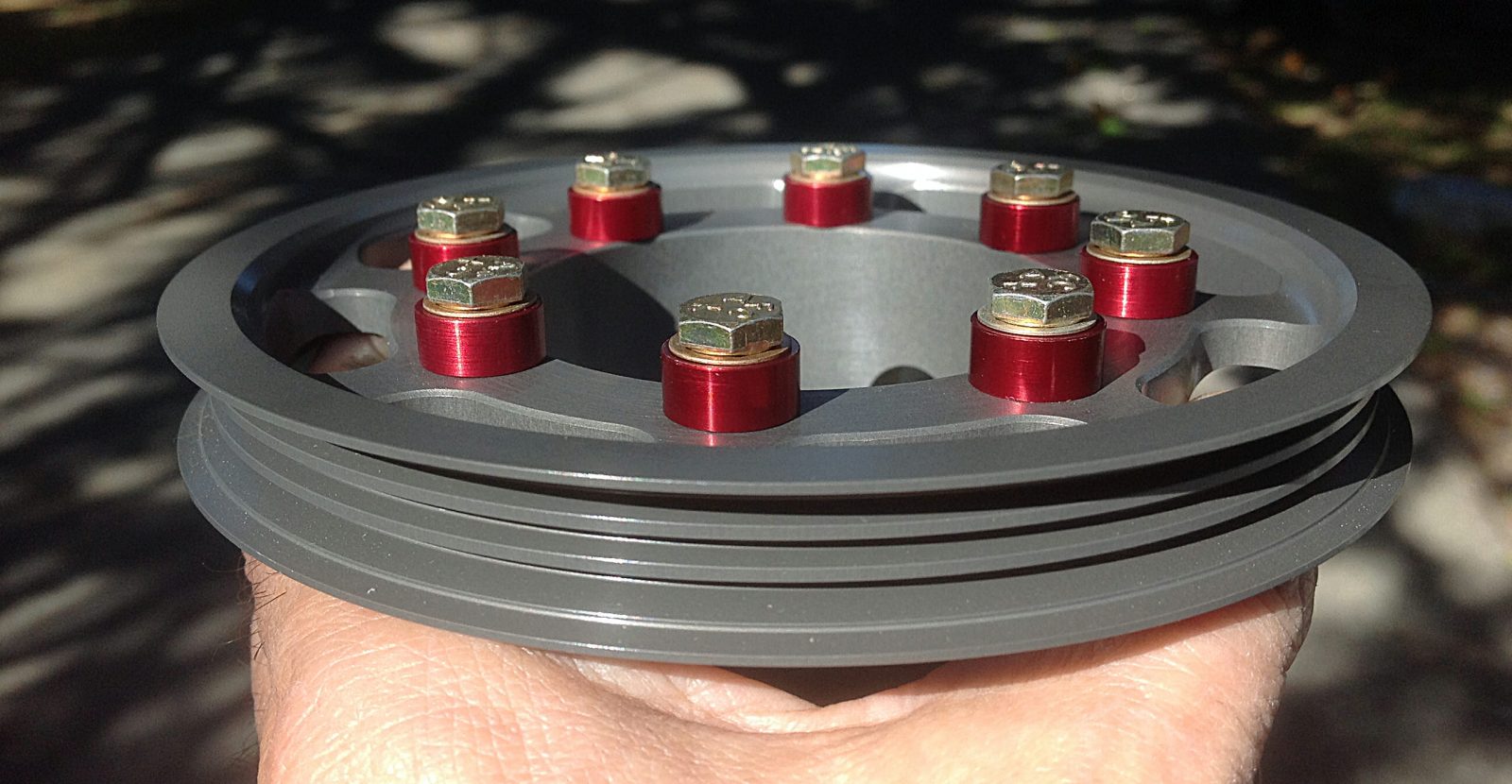

The stock Helicycle kit comes with a 113-Amp riding lawn mower generator system. The full load on the battery bus is almost that much, so I decided to engineer a 55-Amp alternator upgrade. It was a huge project that started with designing a drive pulley and having 20 manufactured of 6061-T6 aluminum that was hardcoat anodized. I sold 18 alternator conversion kits to pay for mine. It took months. This picture shows the CNC- machined pulleys before anodizing. This project took many months to complete…
A finished and hard-coat anodized Alternator Drive Pulley, ready for mounting.
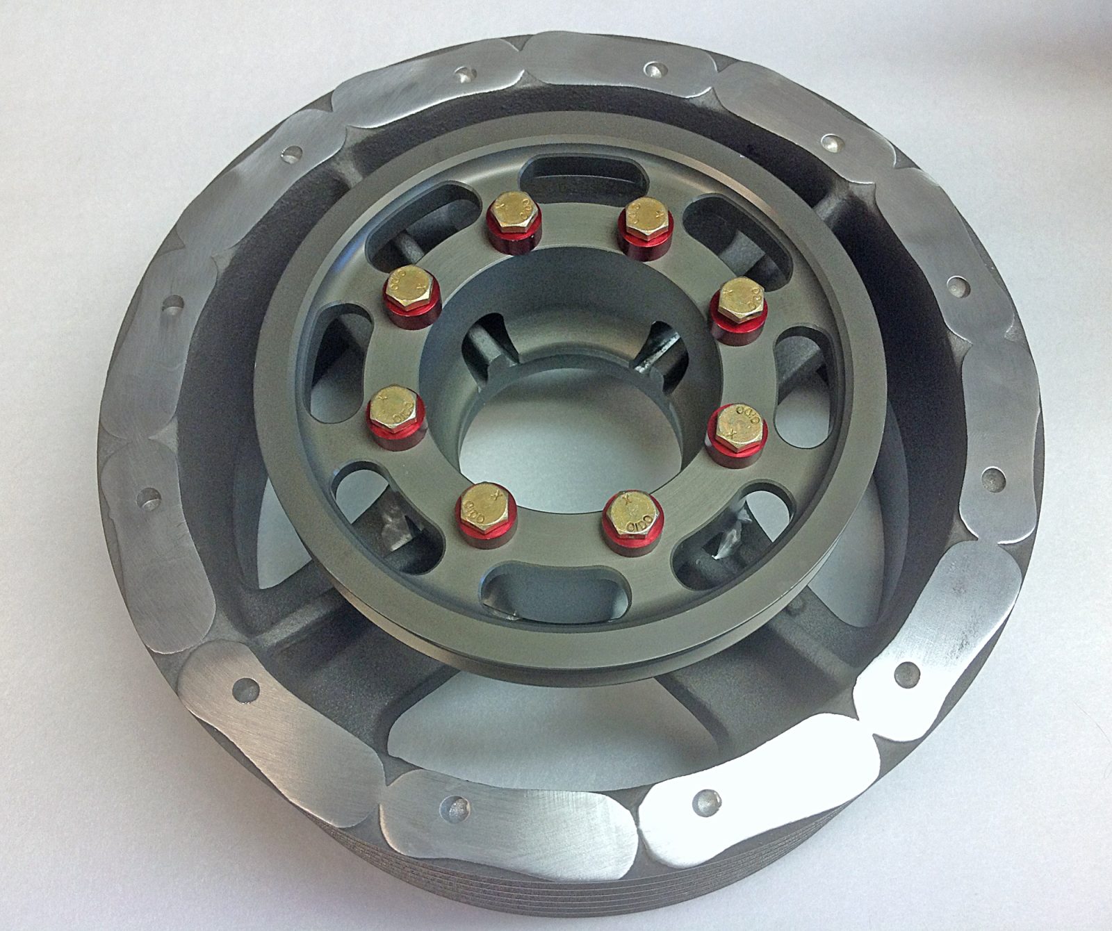
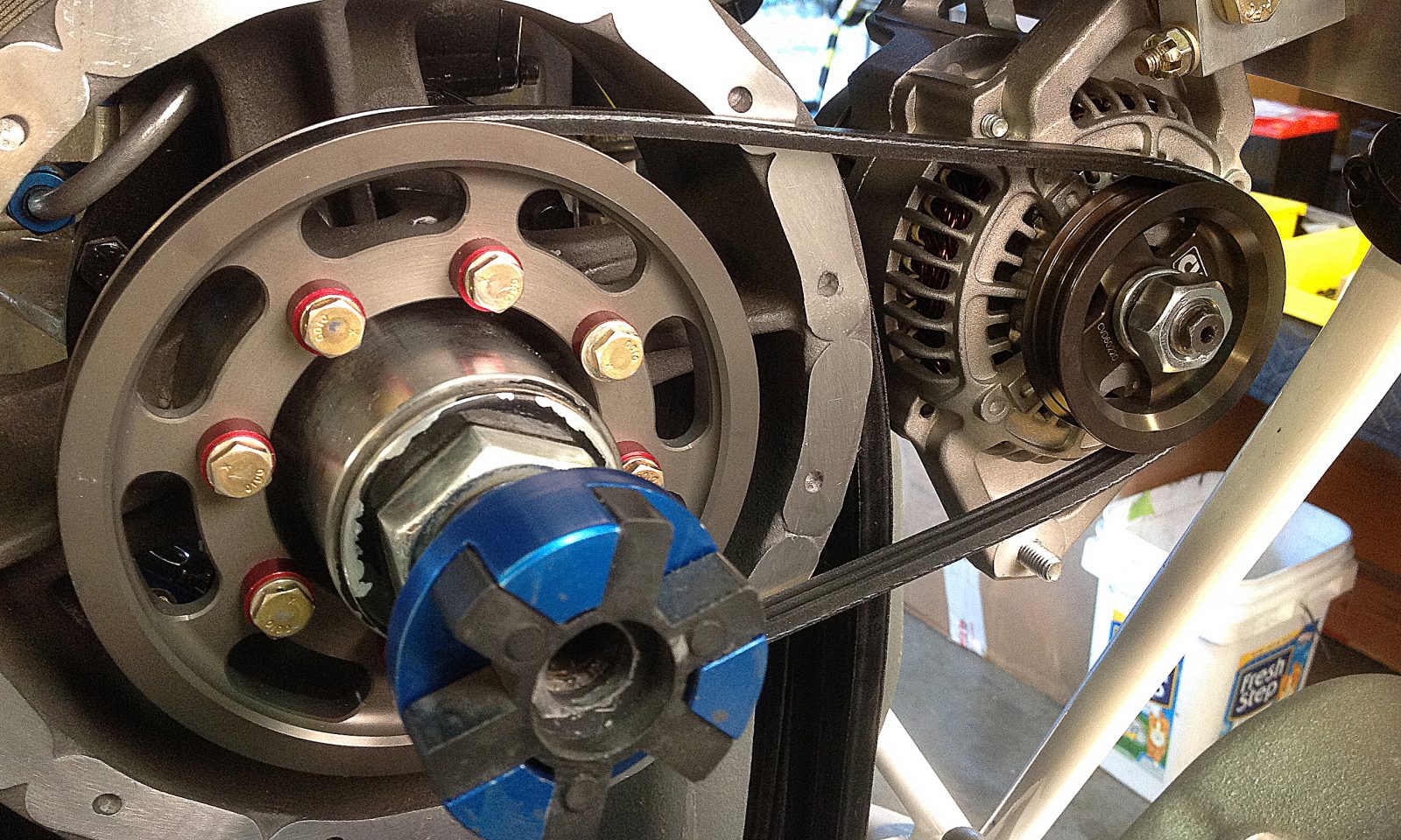
The Alternator Drive Pulley will mount on top of this Transmission Drive Pulley. It was originally designed with fan blade tabs to force air over a radiator before the Solar T62T-32 Turbine Engine was selected. Those tabs were in the way and I had to mill them all off flush…
Here’s that Transmission Drive Pulley with all of the fan tabs removed so the Alternator fan belt will have clear access to the Alternator…
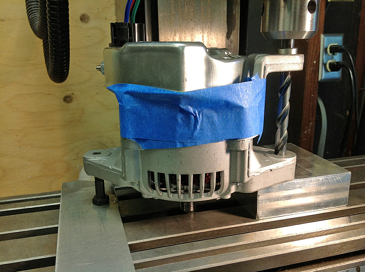
The Alternator also needed to be modified slightly to take phosphor-bronze oilite bearings. This was to reduce friction when the Alternator had to pivot to account for frame flexing caused by Transmission torque…
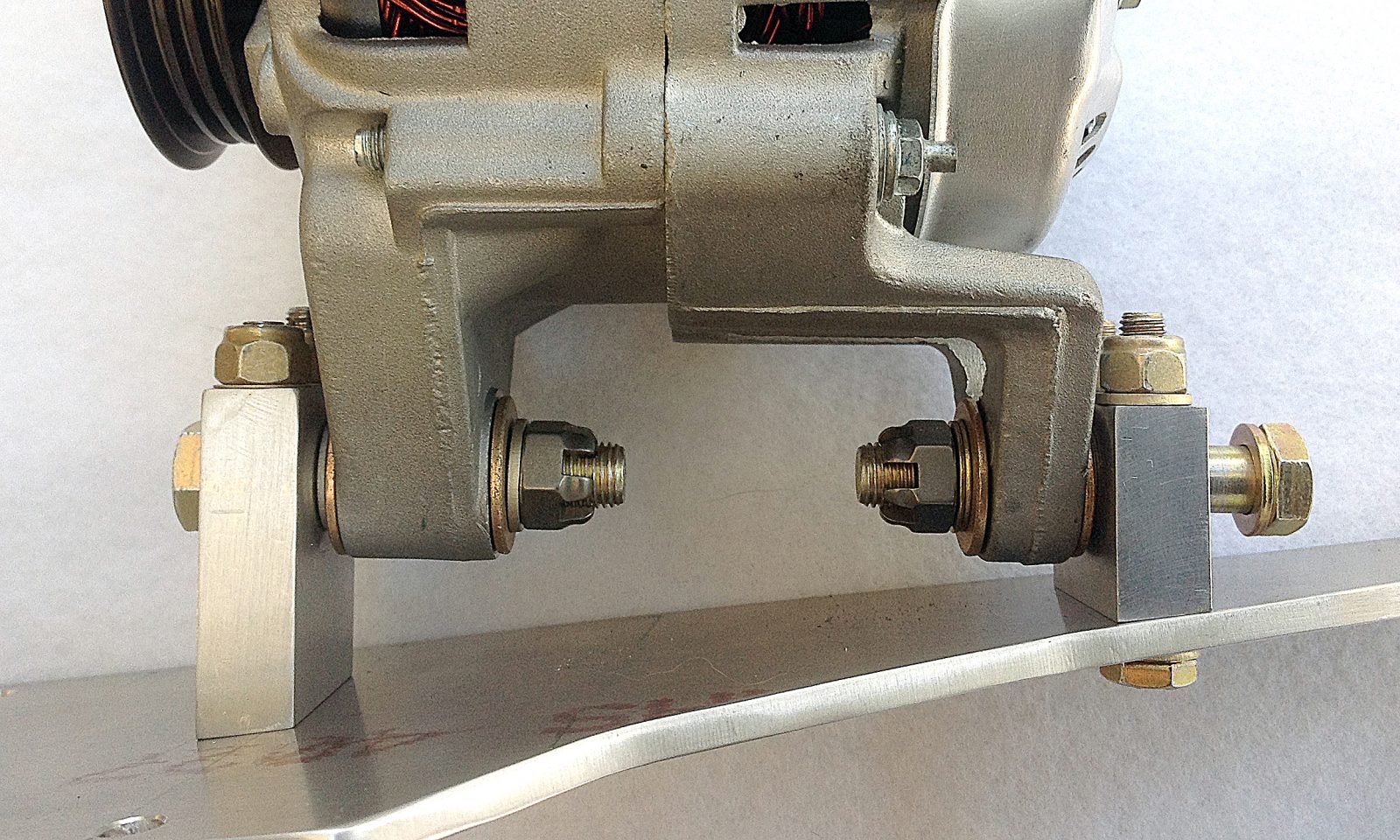
Here’s the finished bracketry. The Alternator will be secured using Castle Nuts and Cotter Pins. I left enough slack so that the Alternator swiveled easily…
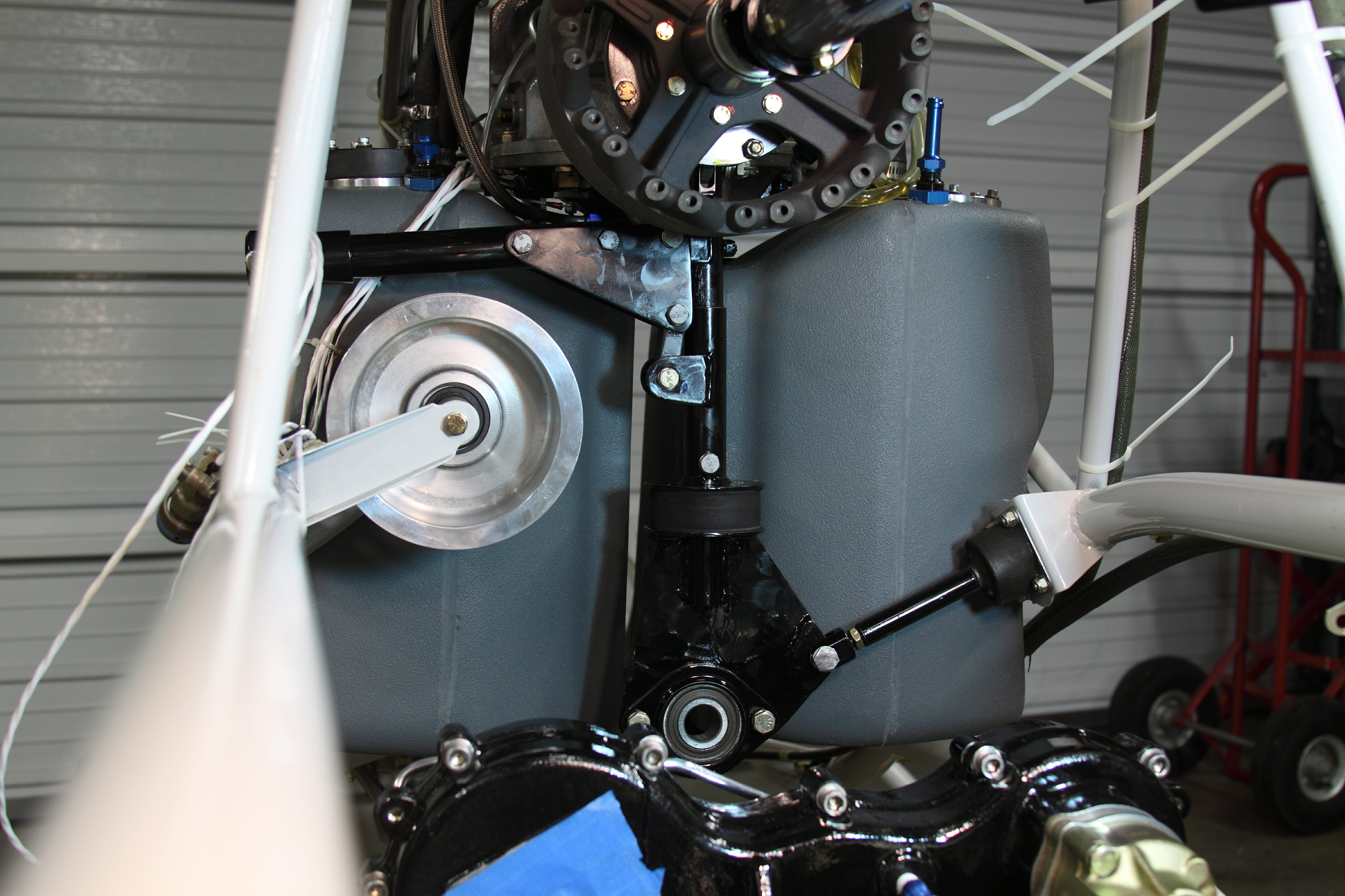
The Alternator and Alternator Drive Pulley are now mounted on the ship. You can see why the Fan tabs needed to be removed from the Transmission Drive Pulley (They were blocking the Micro-V Alternator Drive Belt.)
Not shown in this picture is the Tensioner that kept an even tension on the belt as the frame flexed due to torque.
This project took months to complete and partially explains why it took me three years to complete this helicopter…
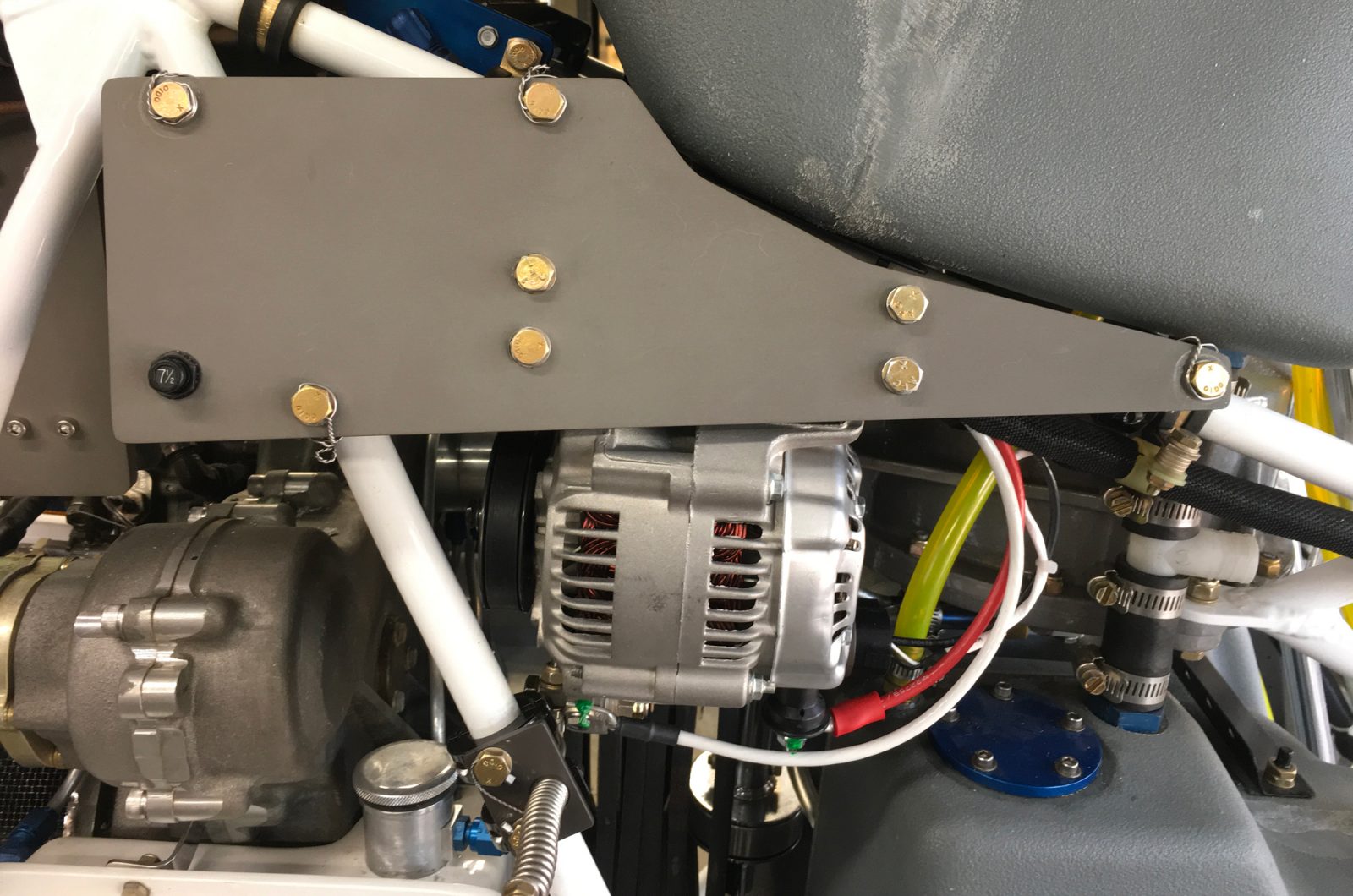
The completed 55-Amp Alternator Upgrade Project – In this picture you can see that the Alternator slopes inward at the sshaft end so that its shaft is parallel with the Transmission Drive Shaft. The tensioner is partially visible at the bottom of the picture…
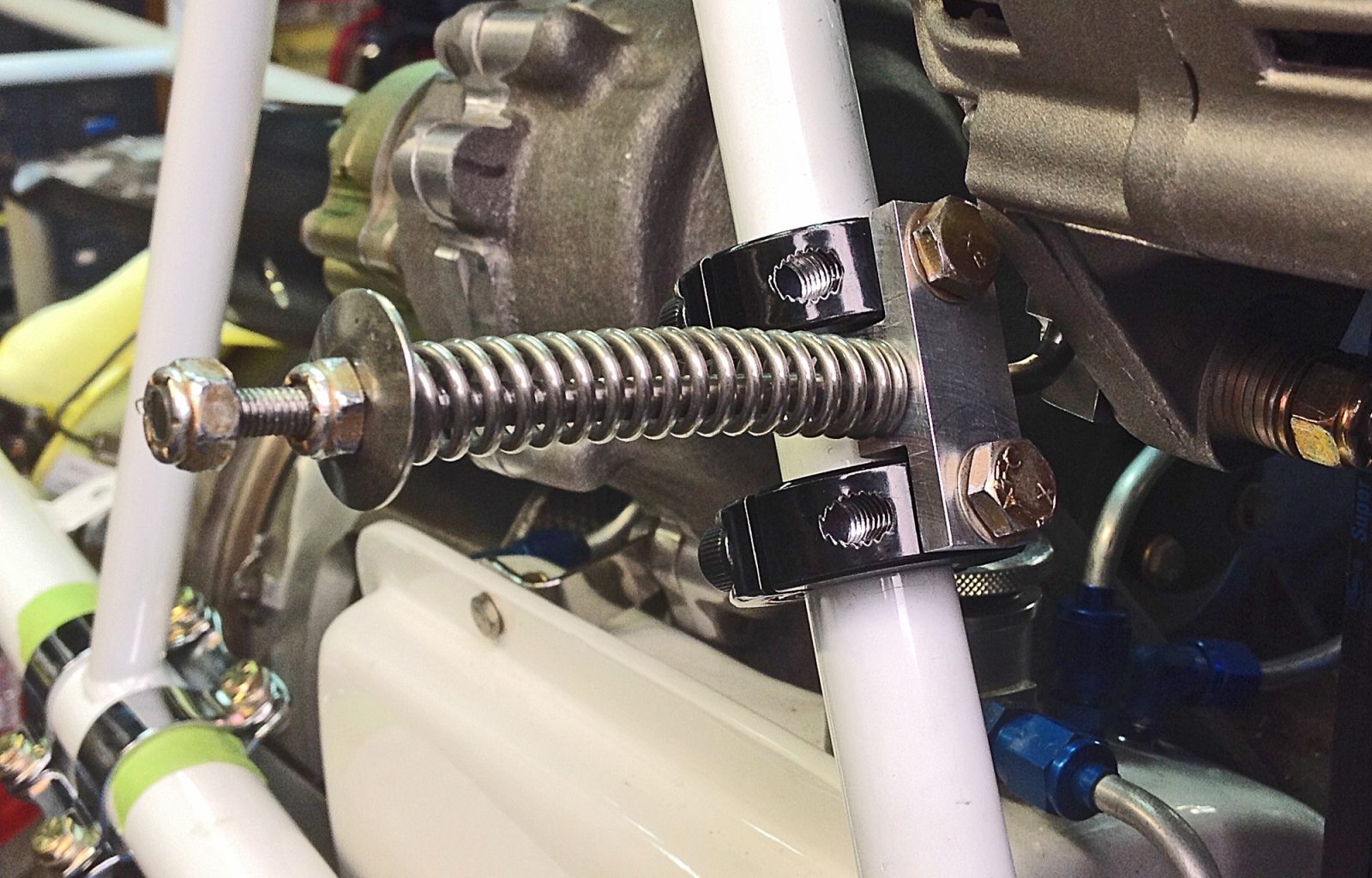
Here’s that Alternator Belt Tensioner. The nut next to the spring adjusts belt tension. The one on the end is to prevent injury if someone bumps into it…
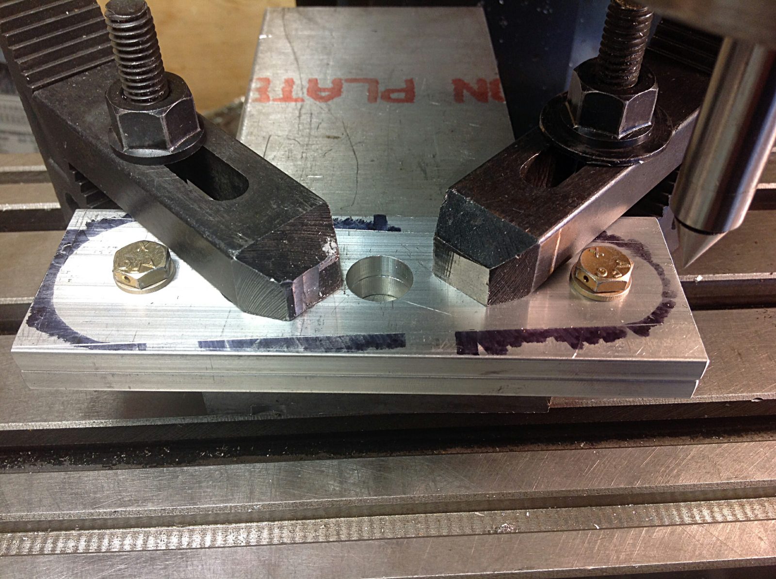
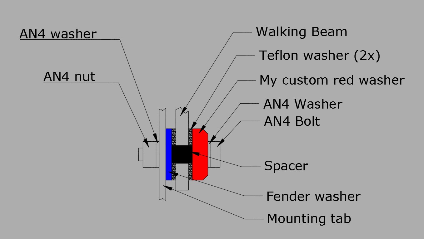
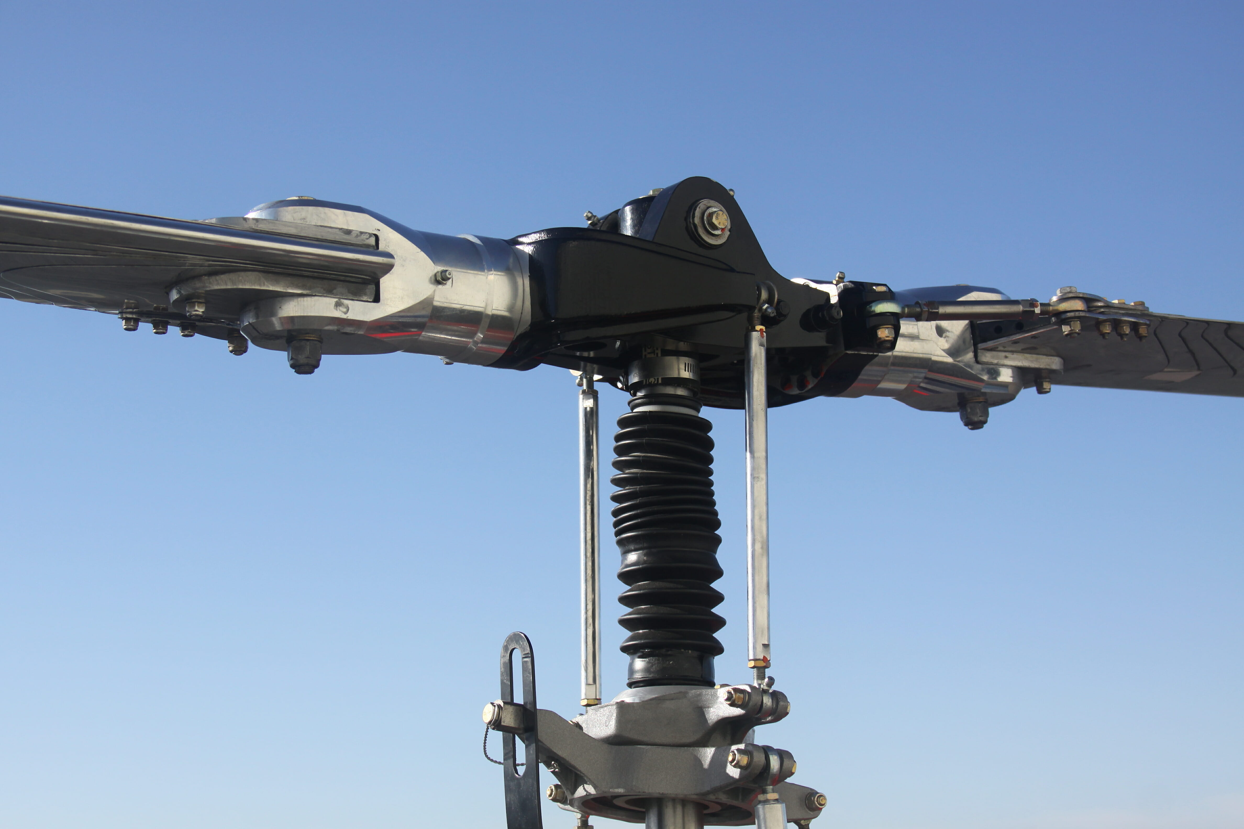
The FAA requires that Amateur-Built Aircraft must construct at least 51 percent of the project. As a result, many of the components must be manufactured by the builder. These two Walking Beams are ab example. The kit manufacturer supplies engineering drawings for most components, but the builder if free to deviate from the design. Of course an FAA inspector must sign off on the completed project before an Airworthiness Certificate is sued. The finished parts are shown on the next slide…
The two teflon washers are compressed in this hardware stackup and act as dampeners to reduce vibration transfer from the rotor system to the cyclic, making for a very smooth ride…
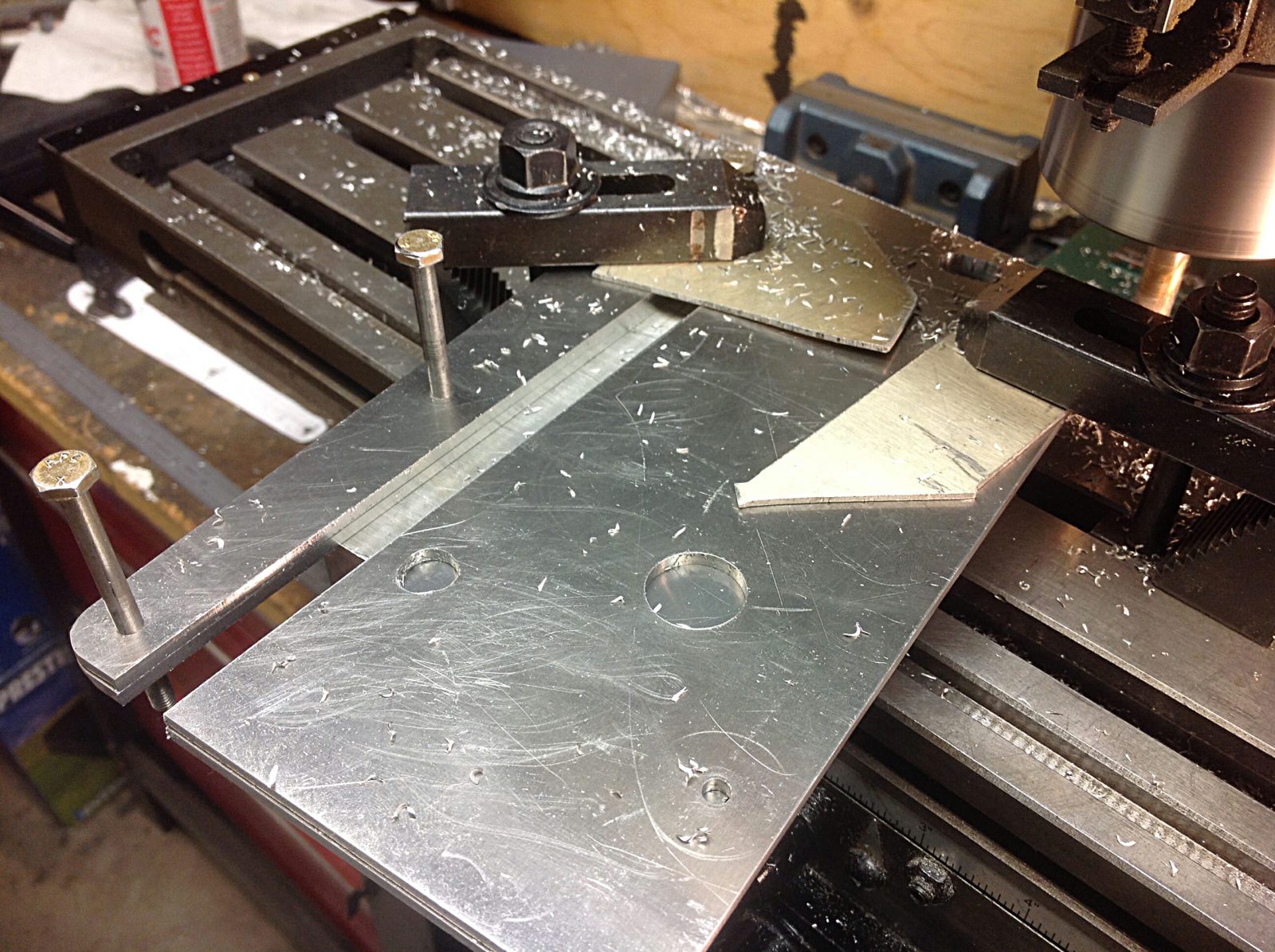
On this, and the next three slides, is another example of components that are left to the builder to fabricate. I used a milling machine for most of my work, but most builders are not so lucky. These particular components are part of the Tail Rotor pitch control mechanism and they are critical. Loose tolerances will affect the handling of the helicopter.
Once the components were machined, they needed to have two compound bends. Once that was done and fit checked thees parts went off to be black anodized…
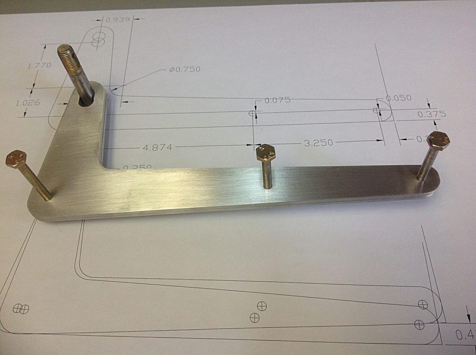
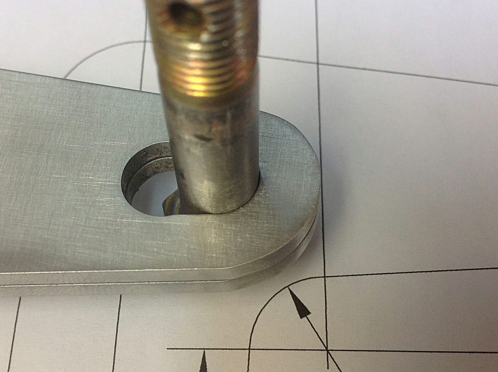
This is an another example of a component that I designed from scratch. The factory solution was too hokey for me. I laid this out using AutoCAD then printed it out 1:1 scale and used that to make a cardboard template. After a few iterations of the design I was ready to cut the part from 5051 Aluminum and bend cut it into shape.
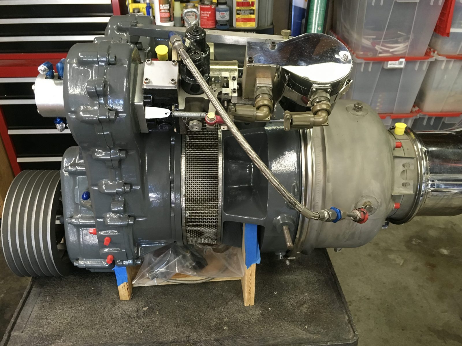
This is one of the major components that come fully manufactured and ready for installation. But there is always work to do, even on these major components. This is the Solar T62T-32 turbine engine. The factory does some mods to the engine and manufactures the gear reduction section (the gray section on the left). I spent considerable time cleaning the engine and then sent it out to be painted Lycoming Gray. I also partially rebuilt the fuel control unit. Everything takes time.
many of the oil and fuel lines are not installed yet. they are also fabricated by the builder…
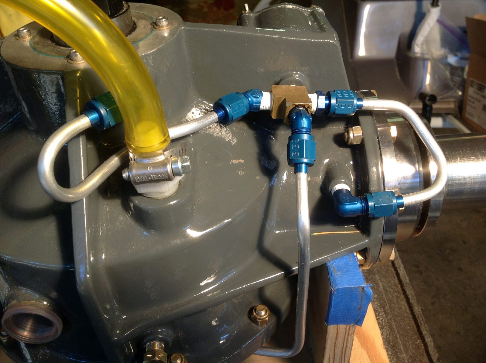
This is a closeup of a section of the Transmission. It has its own oil system, with a pump, filter, and multiple jets to direct oil to critical bearings. All of the oil lines must also be constructed and routed by the builder.
I also had the Transmission painter Lycomming Gray…
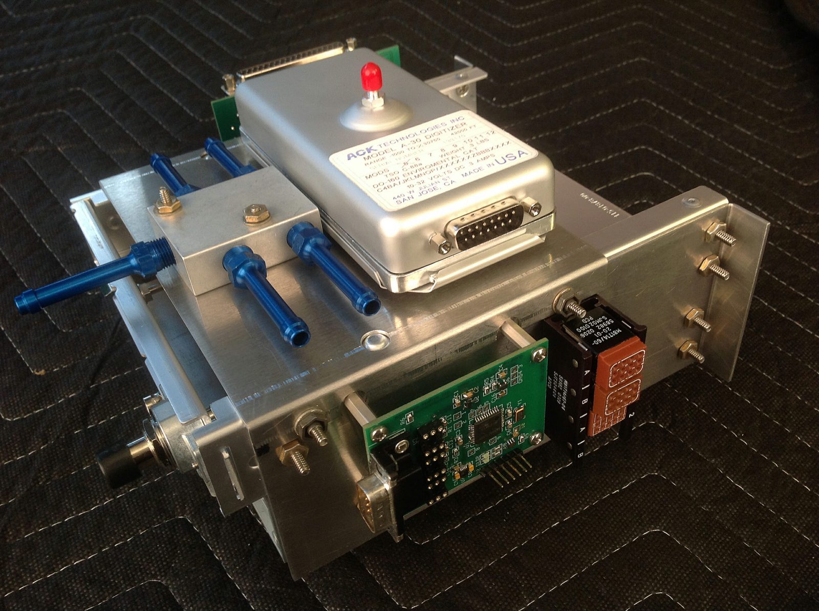
The avionics and instrumentation comprises a huge amount of the labor and it is left almost completely up to the builder. As a result, no two ships are the same. This is a picture of the avionics rack I made from 5051 aluminum to house the VHF Transceiver and Transponder. It also houses the custom Rotor RPM alarm I designed and sold to other builders, as well as other related components…
This picture shows the clutch assembly being installed, and the idler pulley to the left. The picture was taken looking forward from inside the frame prior to engine installation…
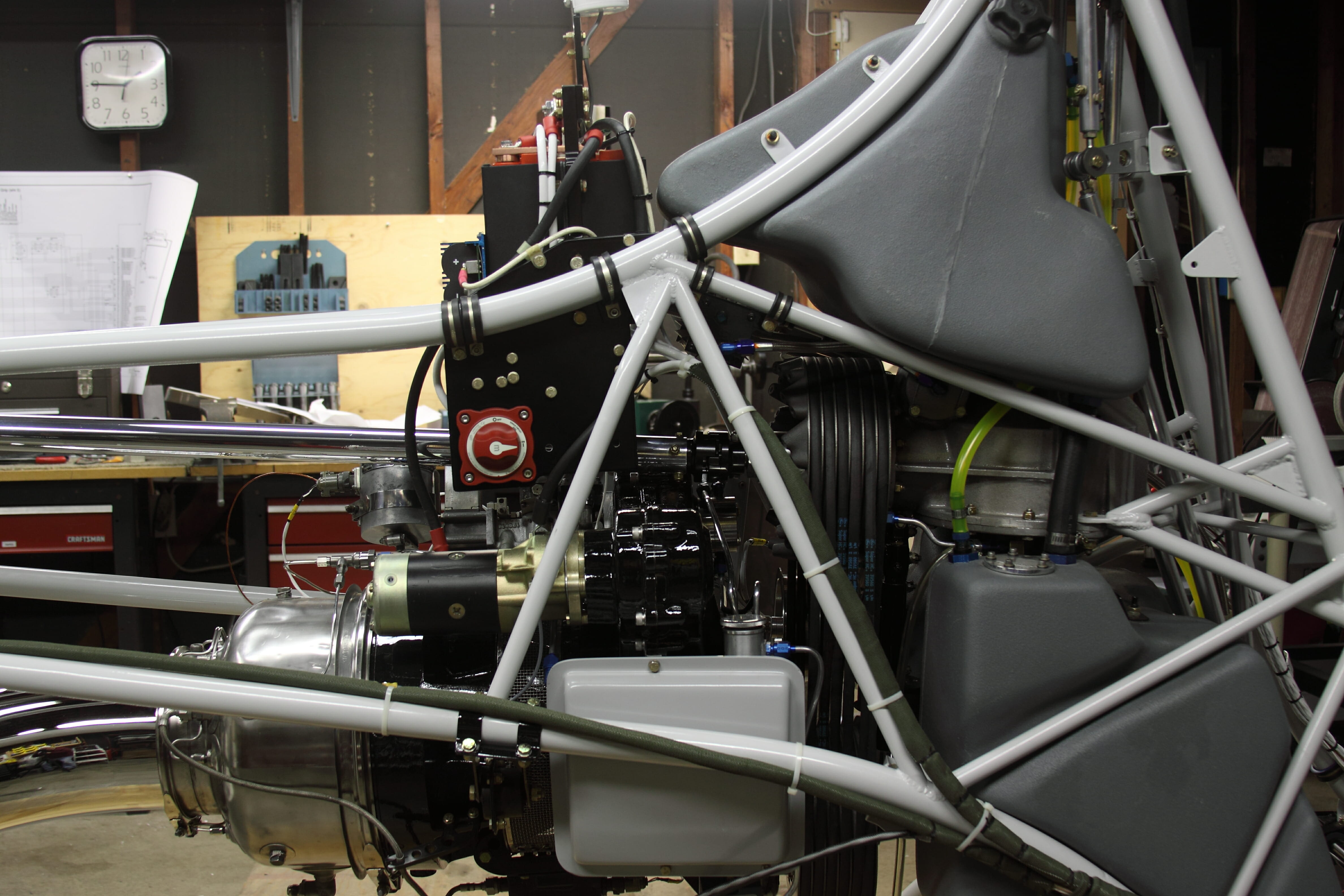
In this picture the engine has been installed, along with some of the electrical wiring. The fuel system is complete and the Transmission is installed. The Alternator project had yet to be started..
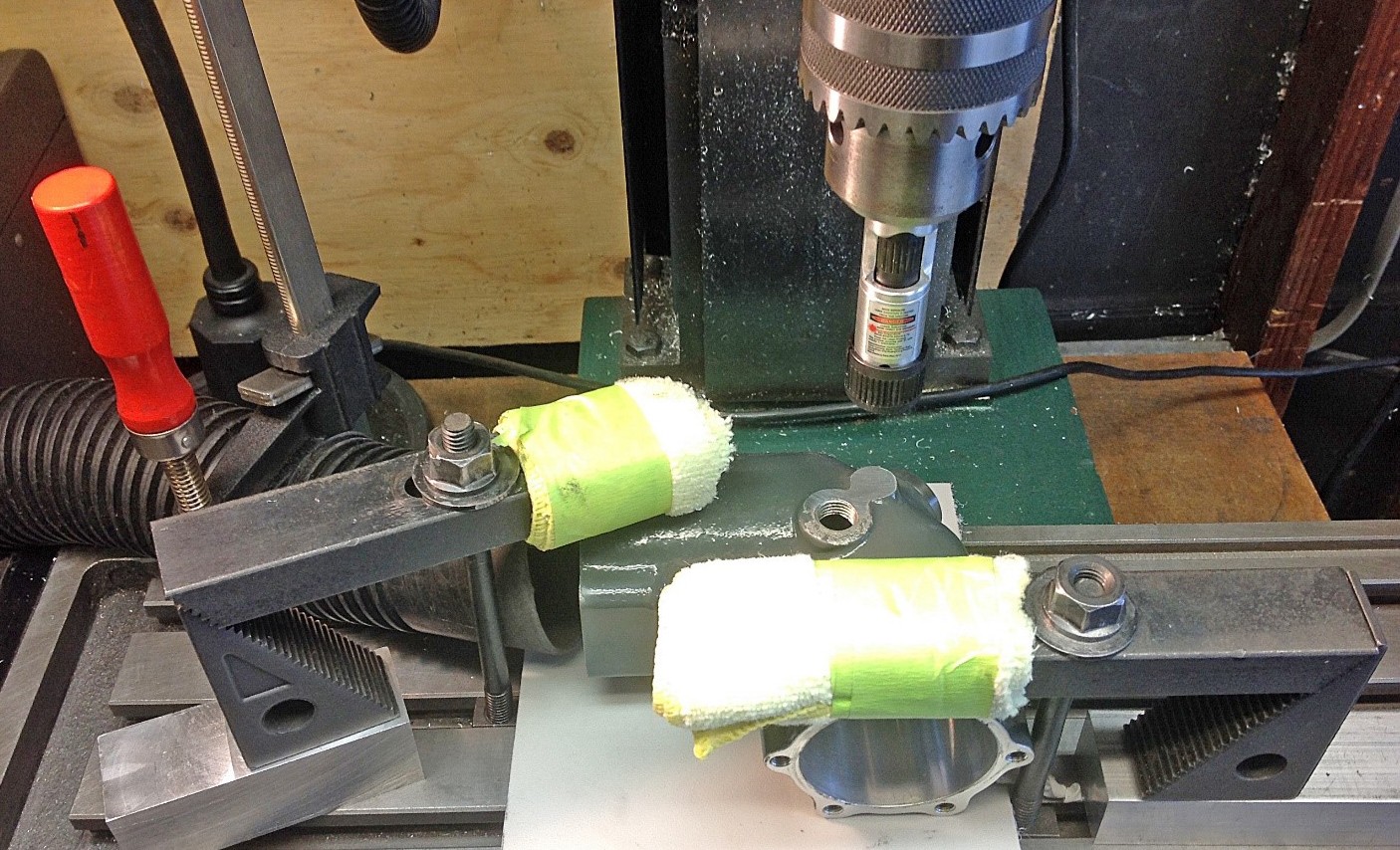
I also added chip detectors to the Transmission and Tail Rotor gearbox. That required some delicate machining.
Here I’m using a laser to line up my mill to drill and tap a precision hole. The main transmission was much trickier to do…
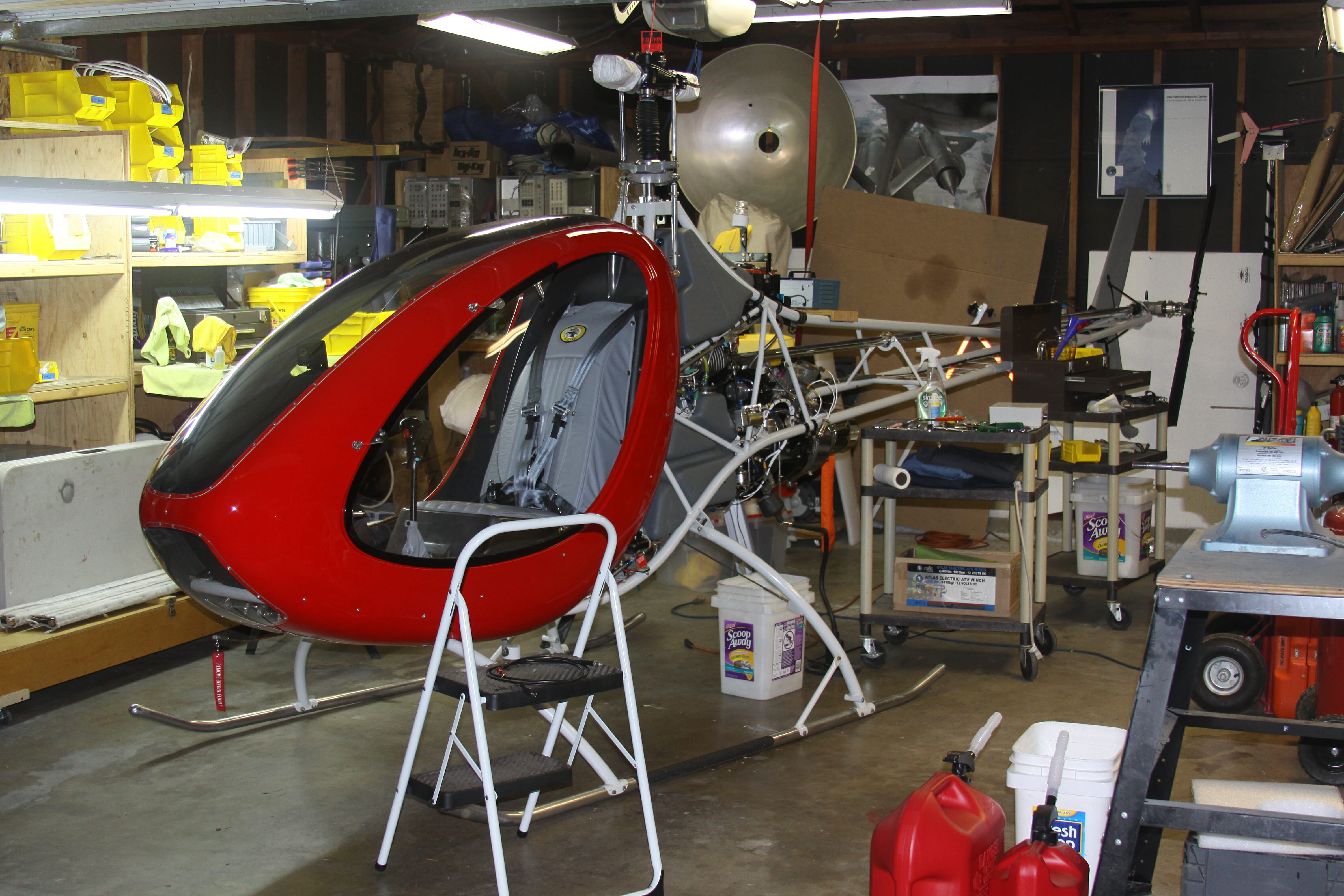
I’m probably about two years into the project at this point. The cabin comes as two rough pieces of fiberglass with Gelcoat on the outside. It took weeks of labor to trim the two pieces to size and get them prepped for painting. The seat is also left to the builder. I found half a cow hide of aviation gray leather and had custom seats made…
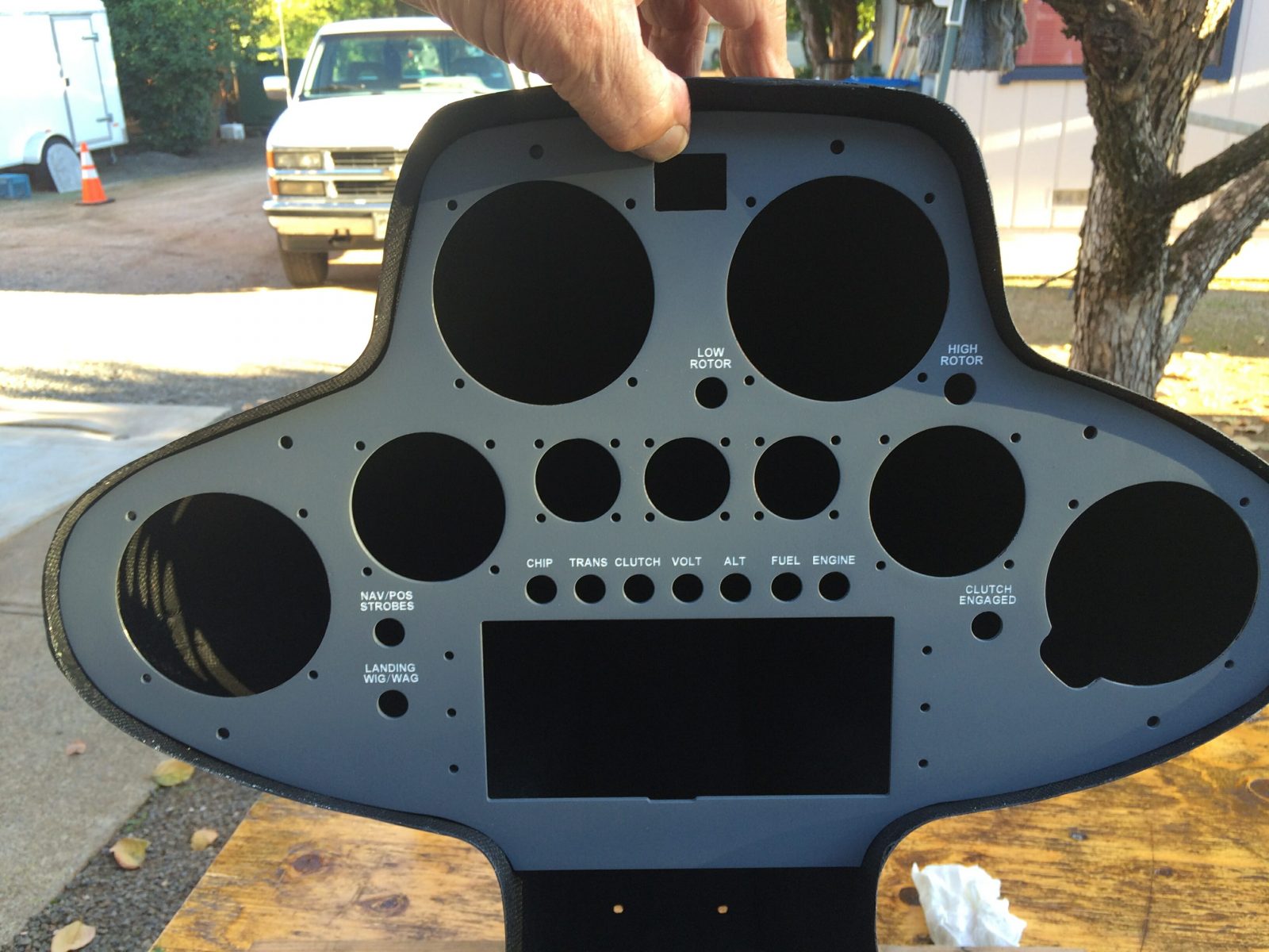
This is my second-generation instrument panel. Since the instrument pod is laid up by hand, it is not completely symmetrical. As a result, these instruments are not exactly symmetrical either. I tweaked their exact location to give a symmetrical appearance. As usual, this was also designed using AutoCAD. The labeling is laser engraved and it came out perfectly!
The remainder of these slides show the progression of steps needed to fabricate and install the absolutely critical lead-lag links on the main rotor blades. Even 0.001-inches of slop in these links would cause big problems.
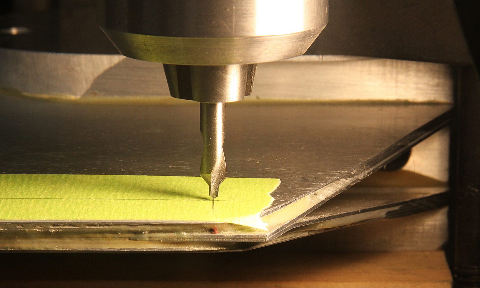
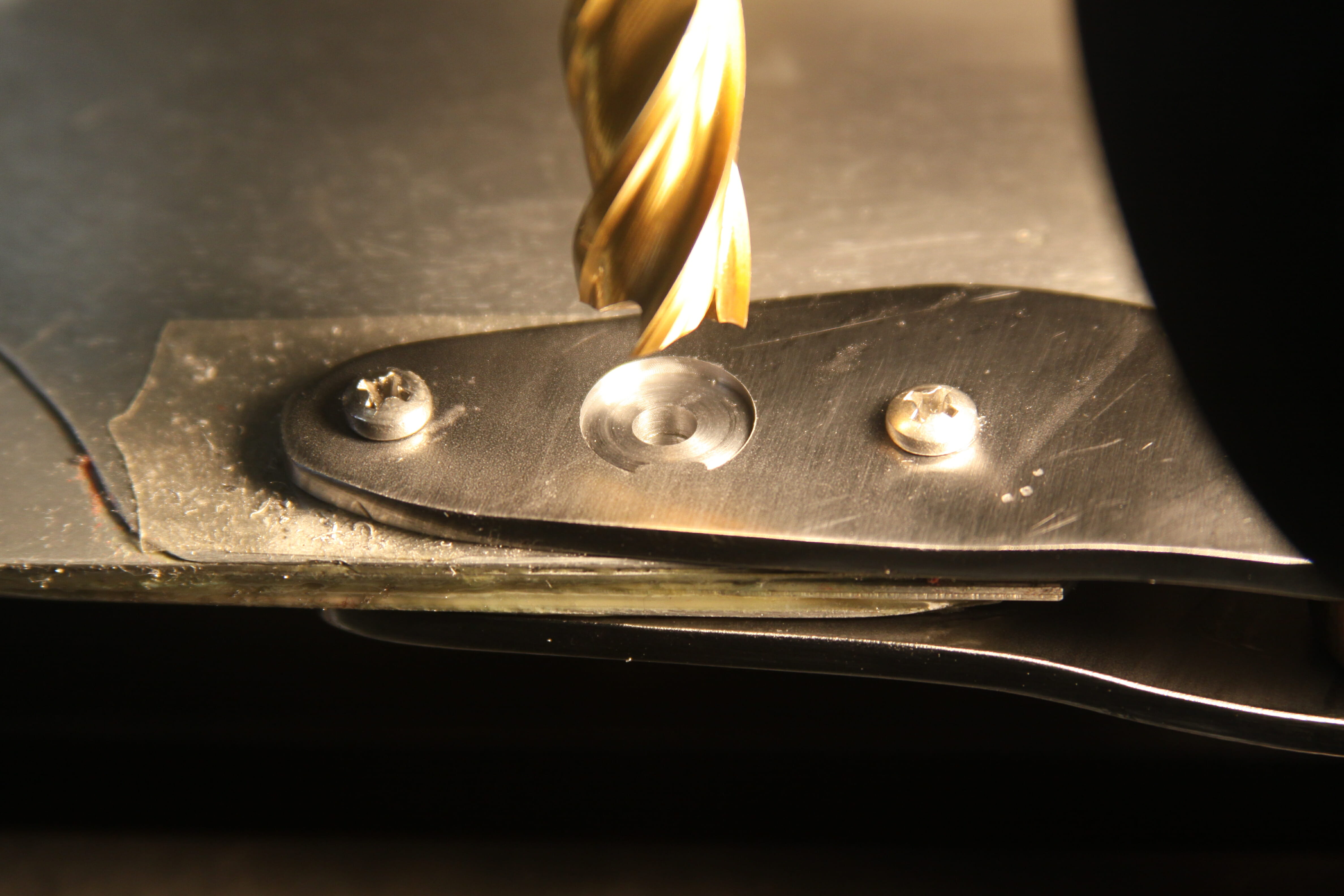
I’m also drilling into a slope which could cause my drill bit to creep, and I also need to surface a pad for the washers to sit flat on the slopped surface. This is typical of the attention to detail that is required to do a good job on this project…
Here I’m using a precision reamer to machine a hole for an AN-3 bolt. These holes have to be snug fits with no slop at all. The bolts should be tapped into position. These machine screws are just temporary to hold the pieces in position…
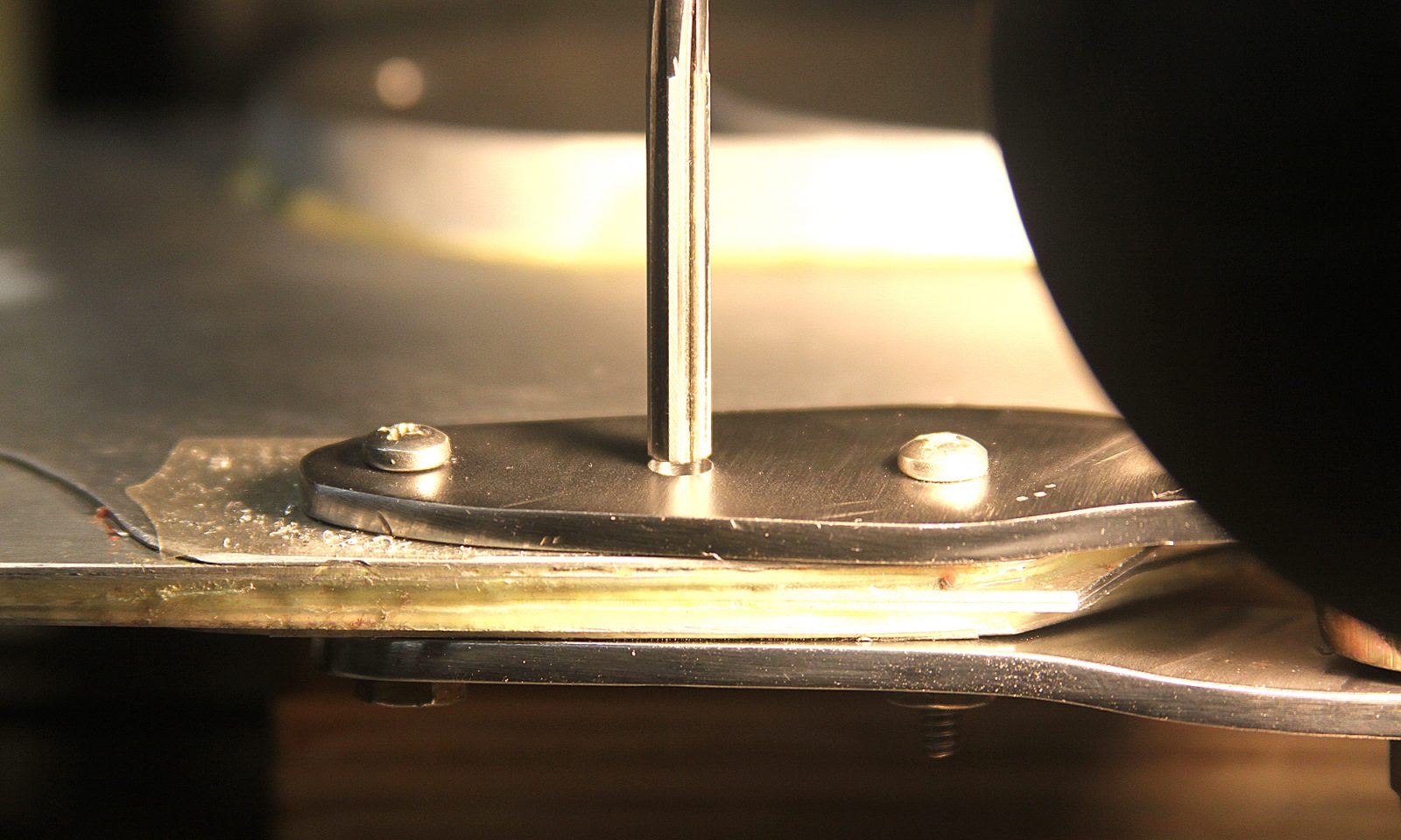
I’m using an end mill to machine a flat for the bolt’s washer. You can see that the far side is indented into the link and the closest side is flush with the surface. This will prevent the bolts from being exposed to an uneven surface…
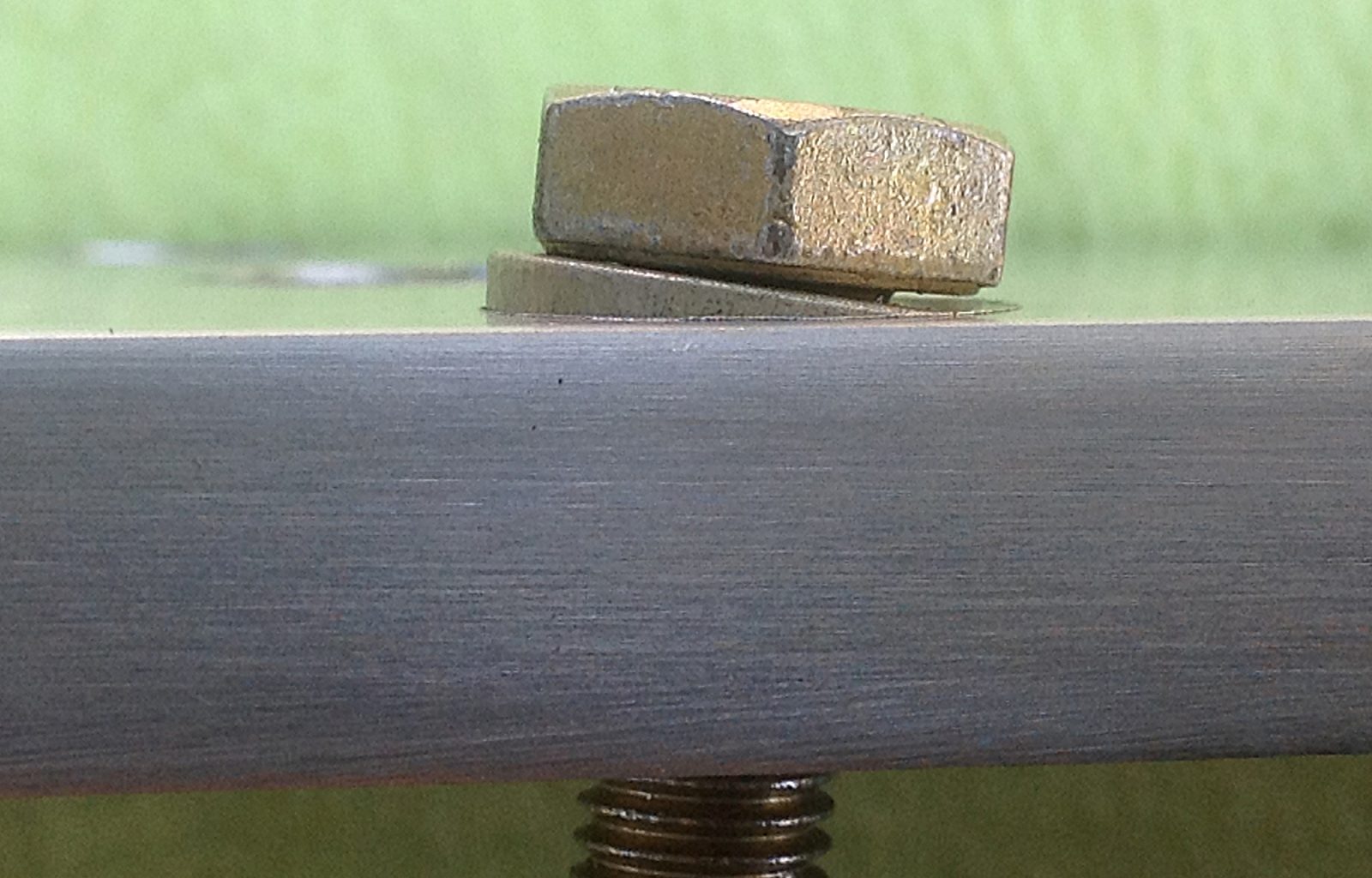
Here’s a side view of an offset counterbore. This allows rthe bolt head to sit flat on top of the washer with the bolt is at an angle…
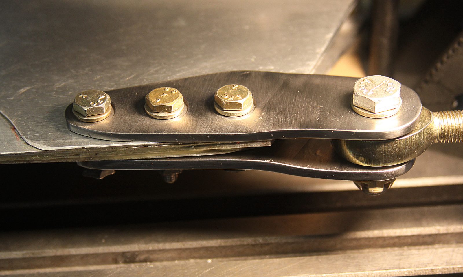
Here’s the completed lead/Lag linkage installed on the root end of a main rotor blade. One down and one to go…
Here’s that Lead/Lag Link installed on a main rotor blade. As I mentioned, even a 0.001-inch change in that linkage will make a huge difference in the dynamic balance of the rotor system. This needs to be perfect…
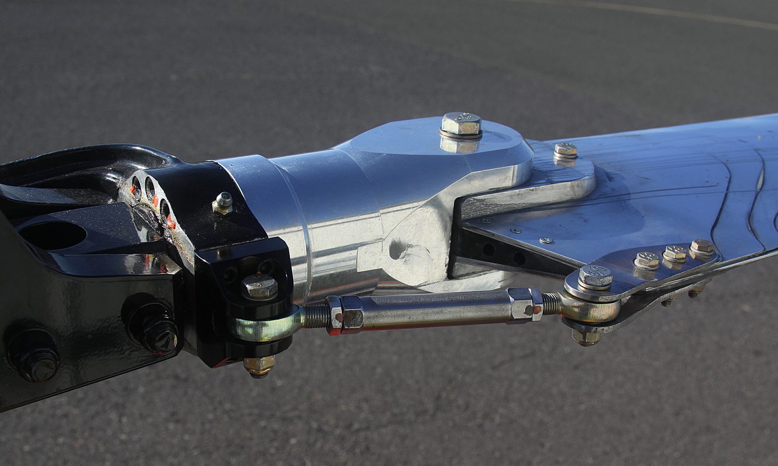
The rotor system is now completely installed and ready for dynamic balancing. Even though the rotor system weights close to fifty pounds, as little as a few grams of imbalance can be easily felt!
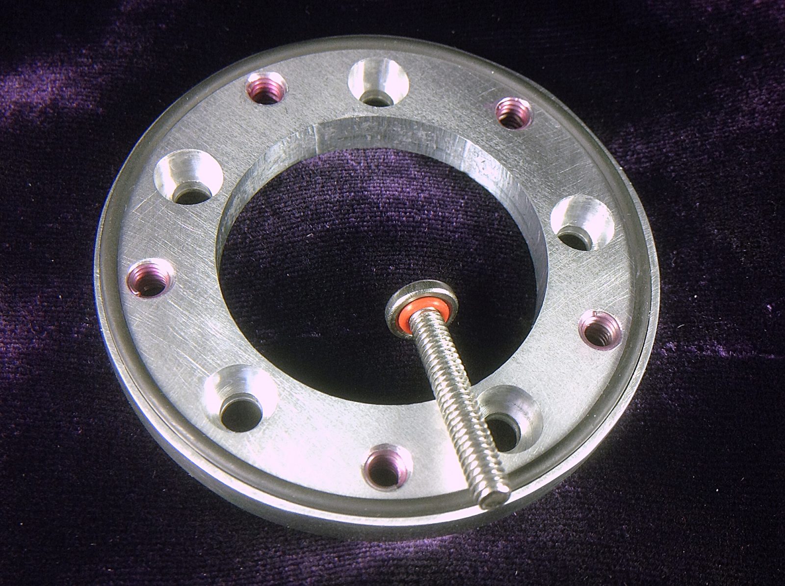
During the past year of my project I had access to a CNC milling machine. Up until I started this project I’d never used any milling machine before. Learning to create CNC-machined parts was a great experience. This is a small interface piece that fits between the Fuel Probe and the Fual Tank. It has an O-Ring on both sides and makes use of O-Ring Sealing Screws to prevent fuel leaks. It worked like a champ and would have been impossible to make in any other way…