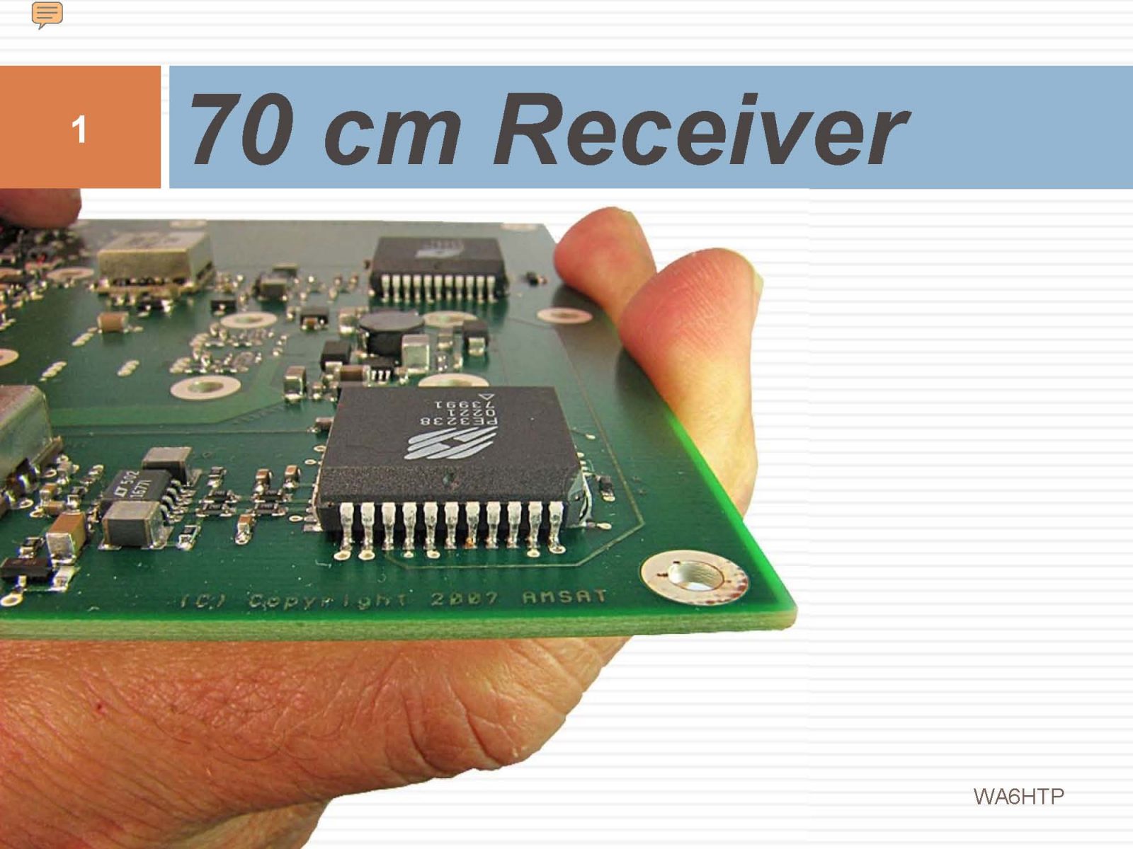
AMSAT RECEIVER


During this multi-month project we developed a solder reflow capability based on a Toaster Oven, and did advanced thermal testing using a modified Microwave Oven. I developed a number of control and monitor applications using LabVIEW. We also caught some serious problems that slipped through the cracks due to a lack of thoroughness in other areas. Space is unforgiving and attention to detail is critically important.
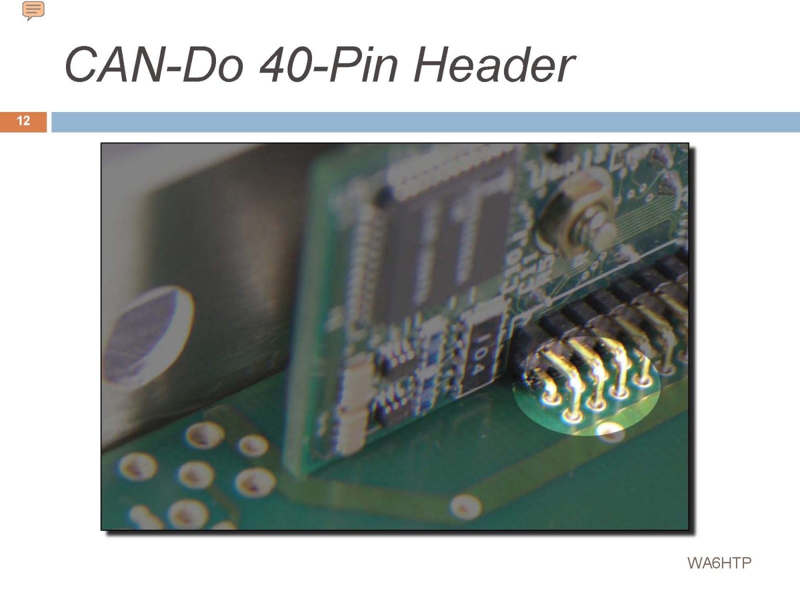
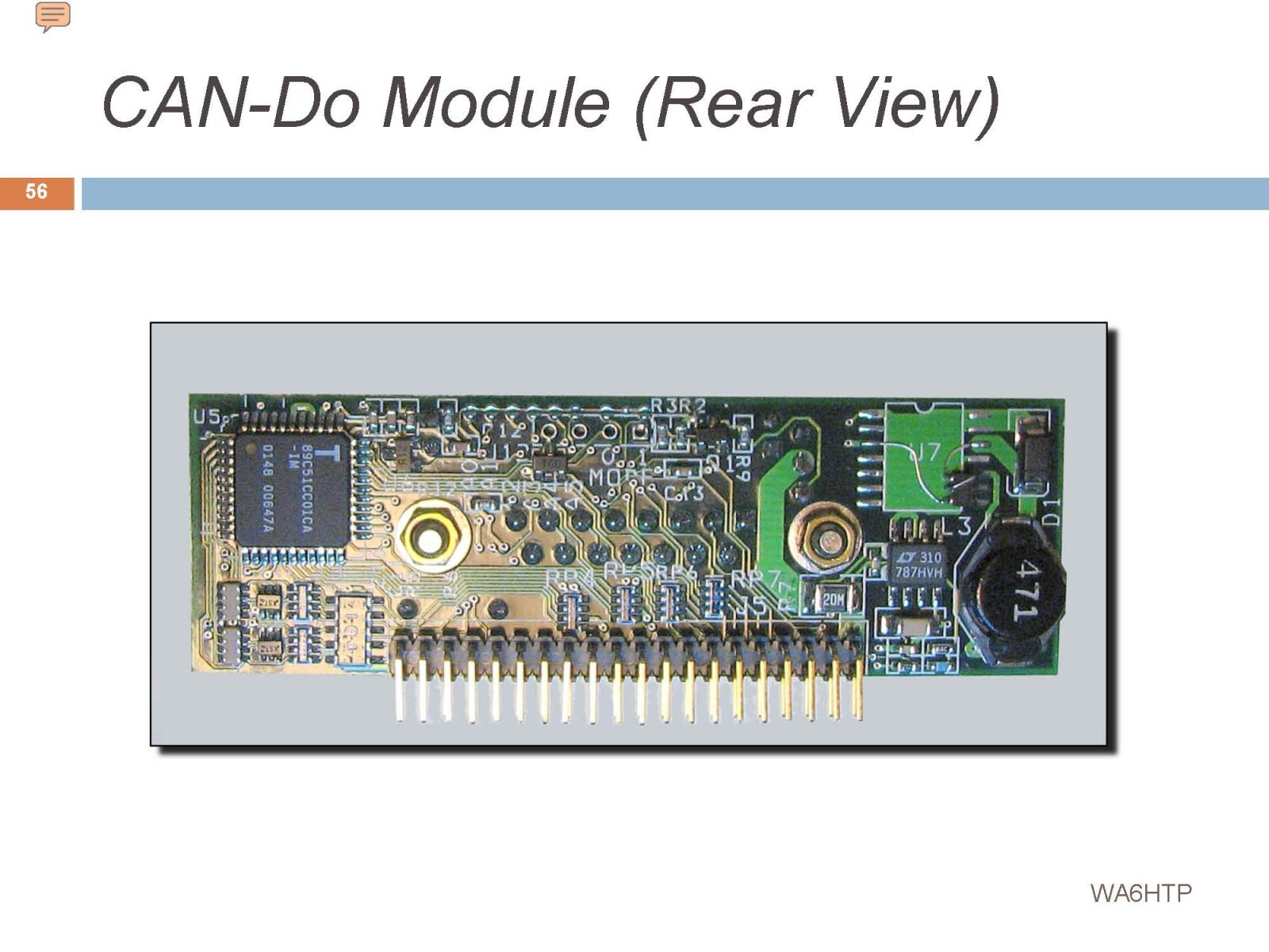
The CAD-DO Module was at the heart of the spacecraft and was the communication interface between subsystems. It used the Automotive CAN bus and was thought to be completely mature and ready for space. We discovered that it had big problems with radiated and conducted EMI. It may have been a tipping point in the Eagle satellite’s demise.
As you can see, this module was absolutely critical to the success of the project. Unfortunately we discovered that it was seriously flawed and needed a major rework.
One major concern with using 70 cm as the command uplink band was possible interference from PAVPAWS – an extremely powerful military radar system.
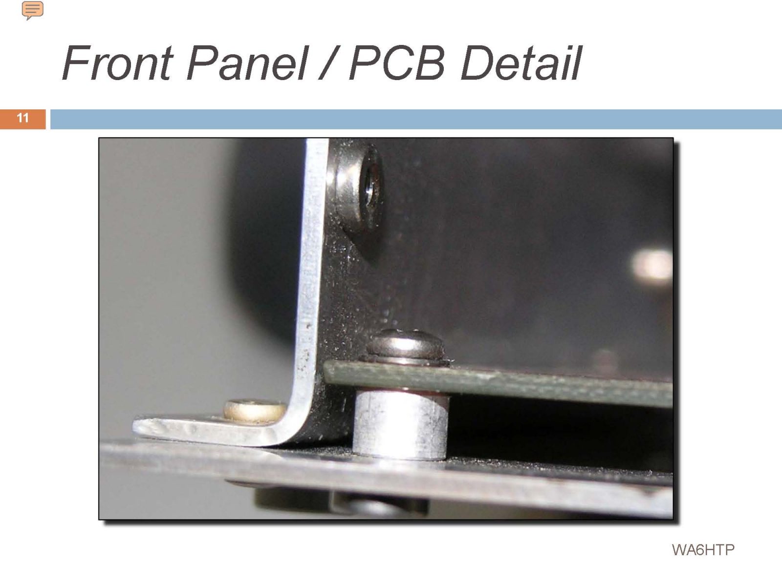
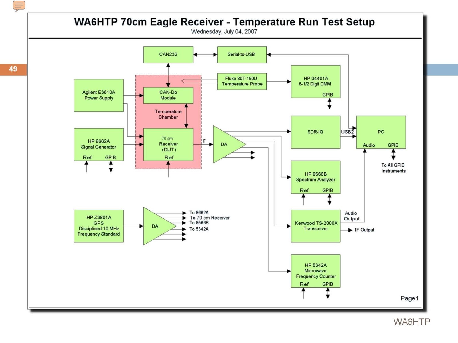
Since the enclosure and CAN-Do module had already reached maturity before the Receiver project was started, there was no flexibility in placement of that module. This added to the EMI problems that soon surfaced…
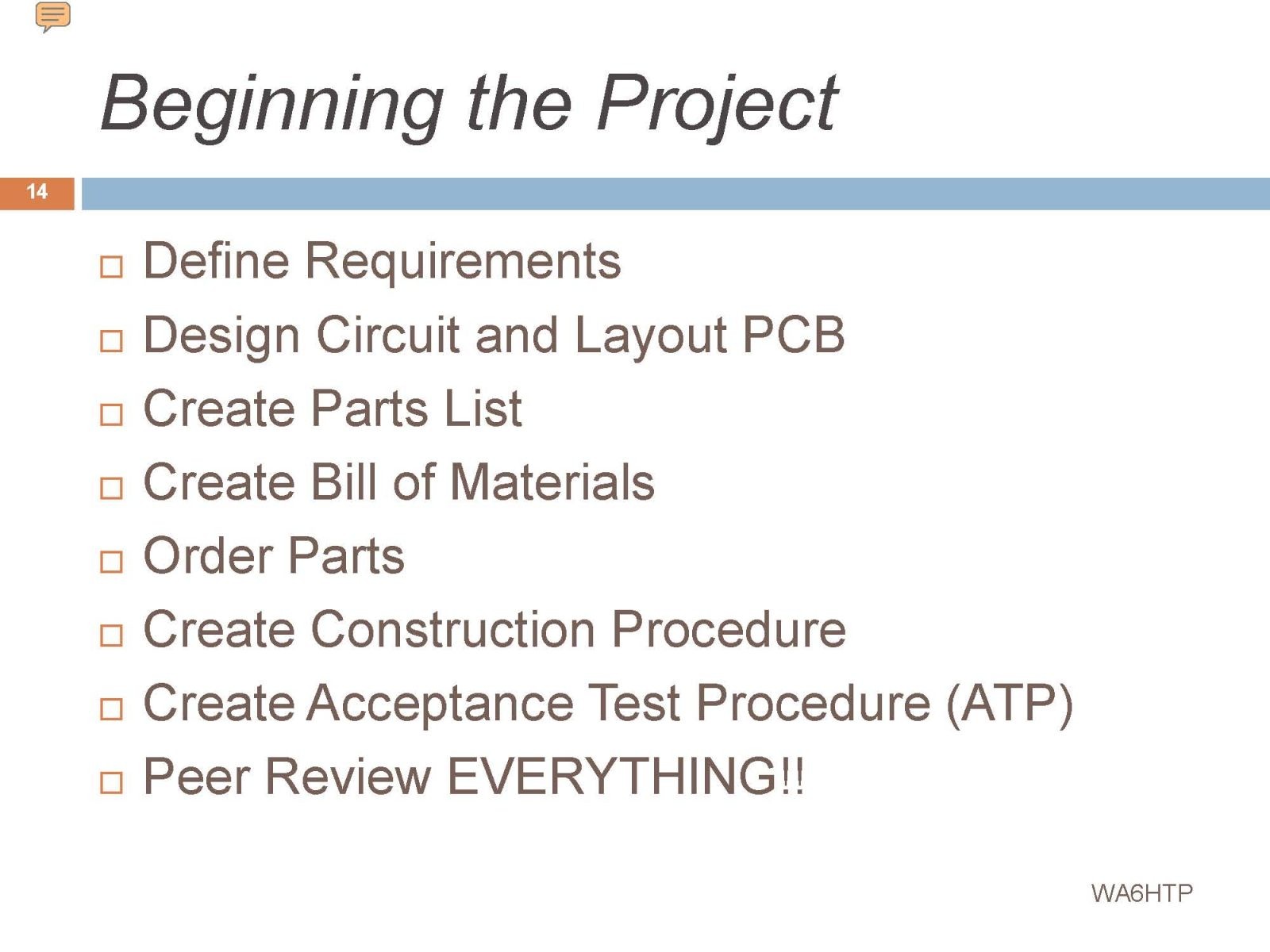
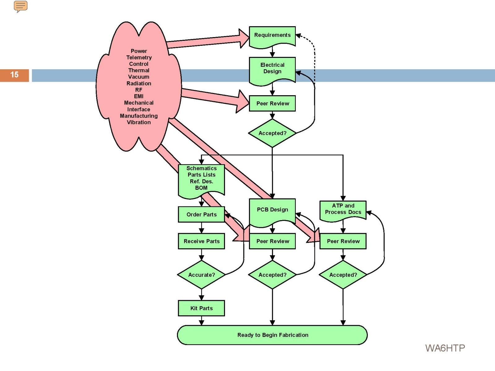
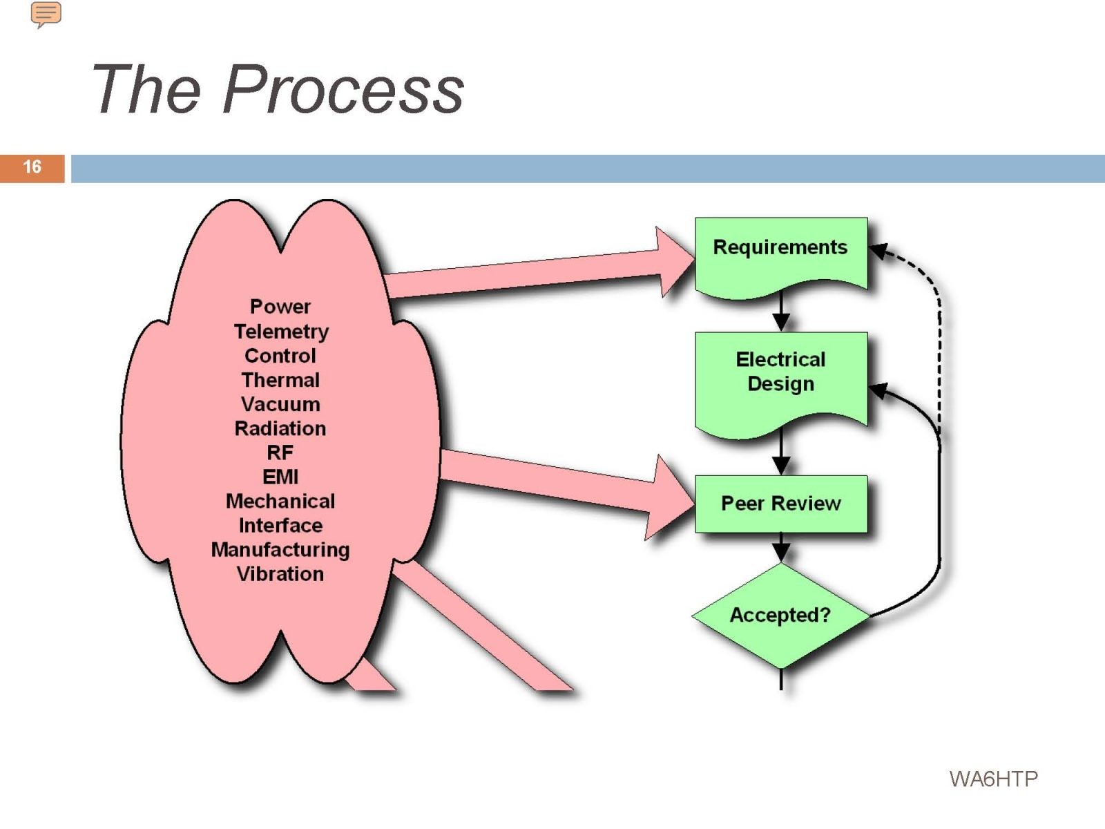
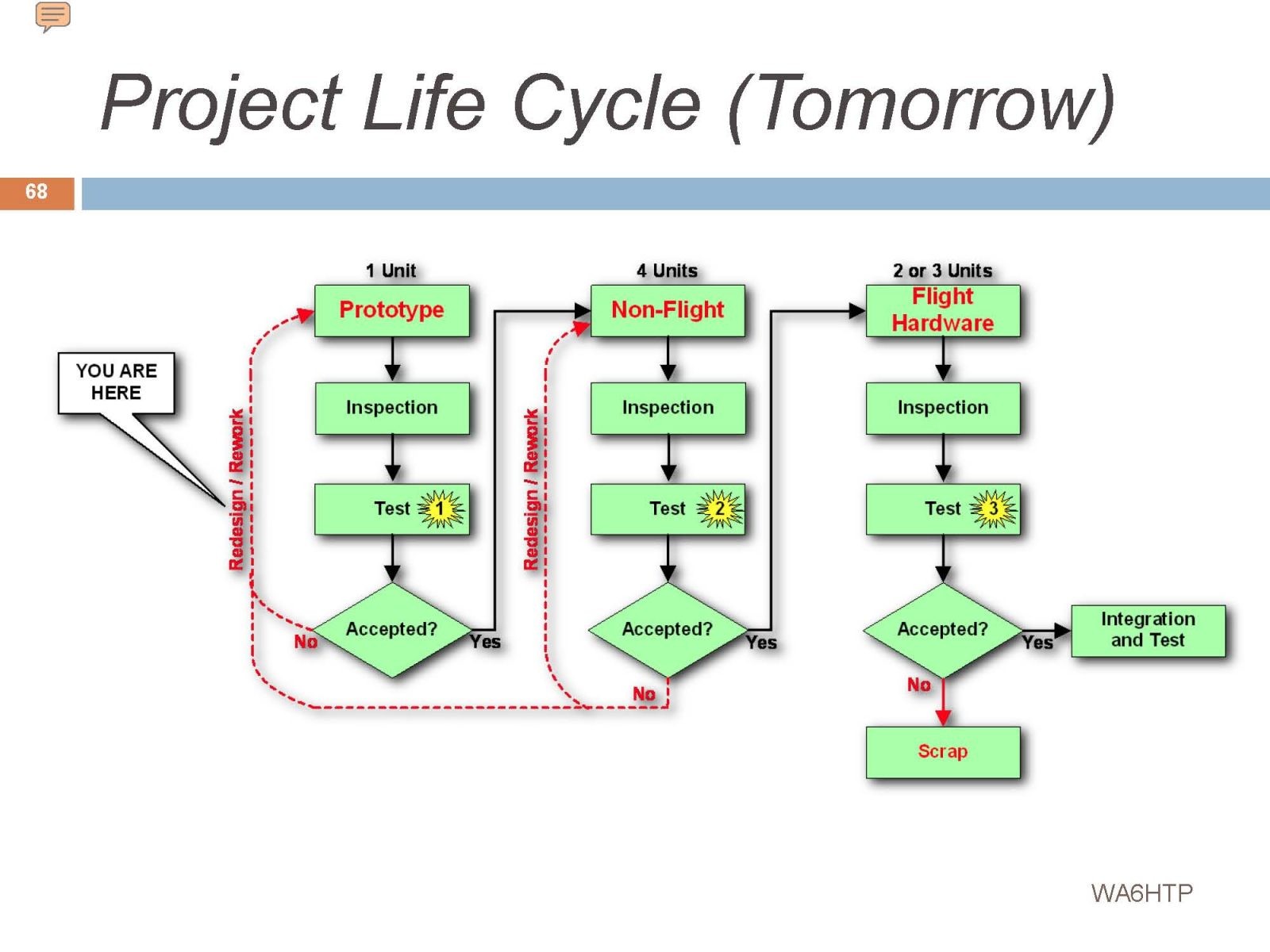
Normally there should have been a peer-reviewed set of detailed requirements for this receiver. Since none existed we had to come up with our own and hope we didn’t miss anything. Not a good way to start! This flow chart is my effort to manage this important step. Everything flows from the requirements.
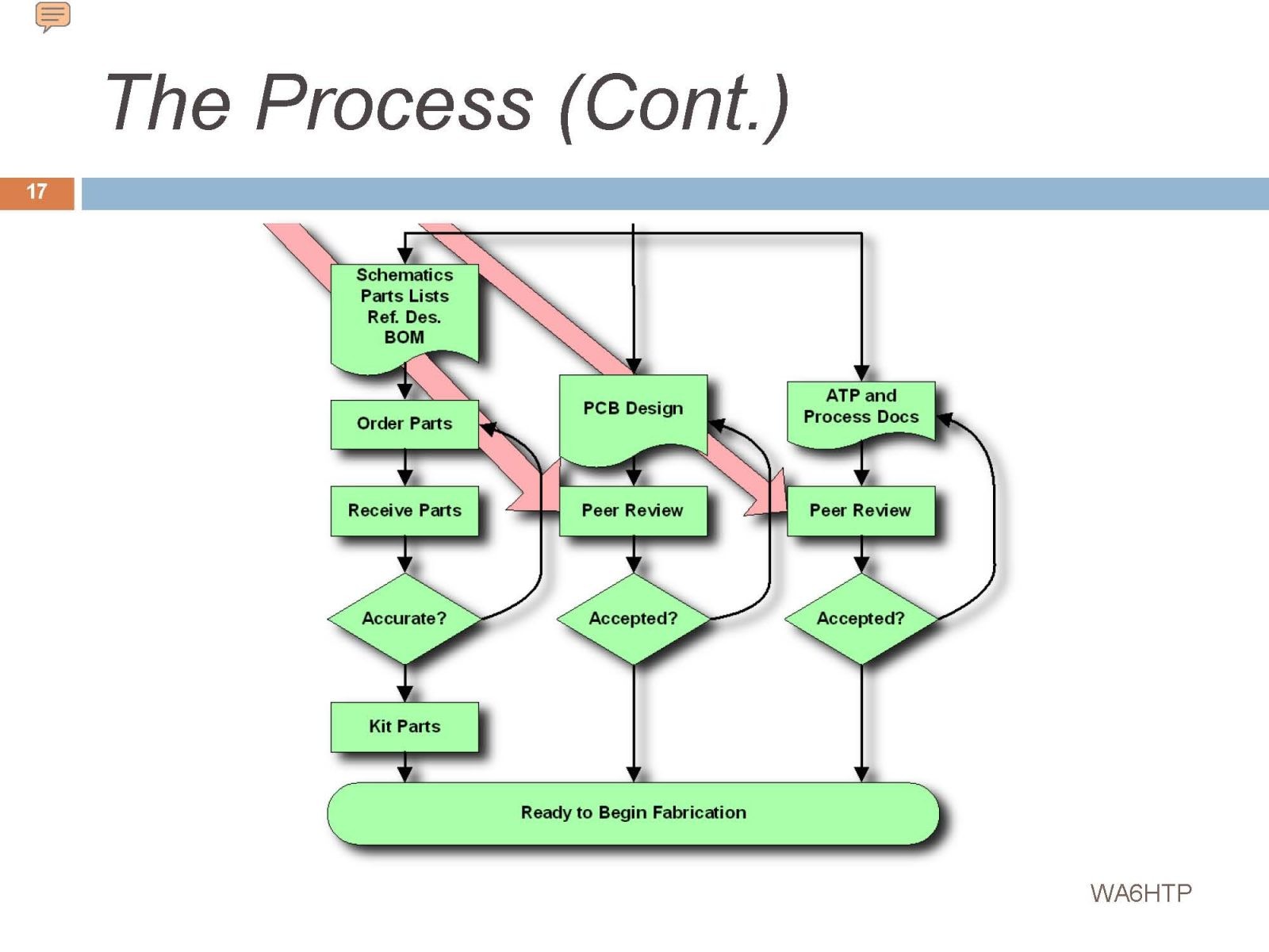
Everything flows from the requirements that were missing. Notice that in my flow chart fabrications of the receiver is at the very bottom of a long list of critical steps.
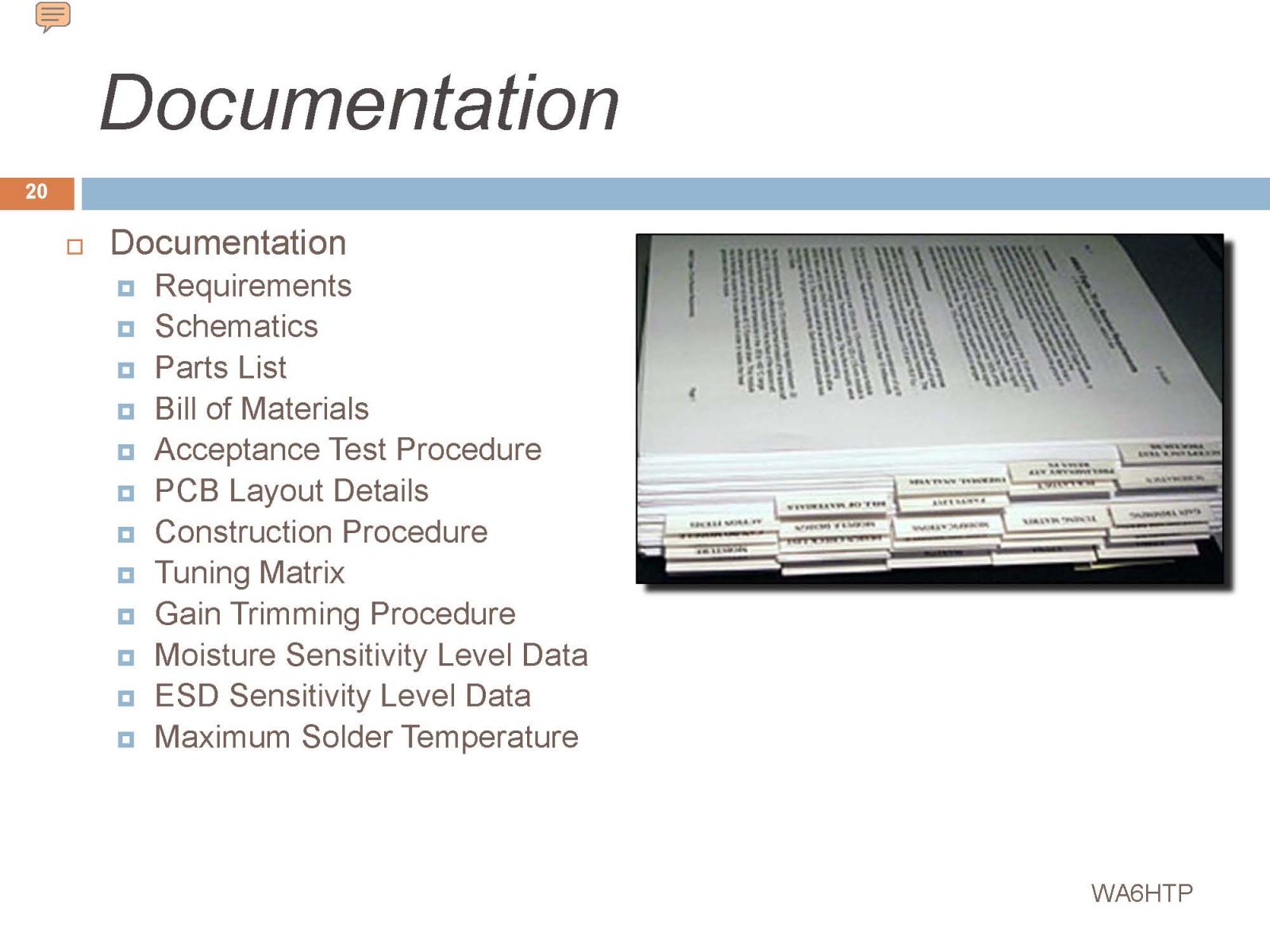
Almost ready to roll up our sleeves and start construction. That binder represented a huge amount of work, but it’s all necessary.
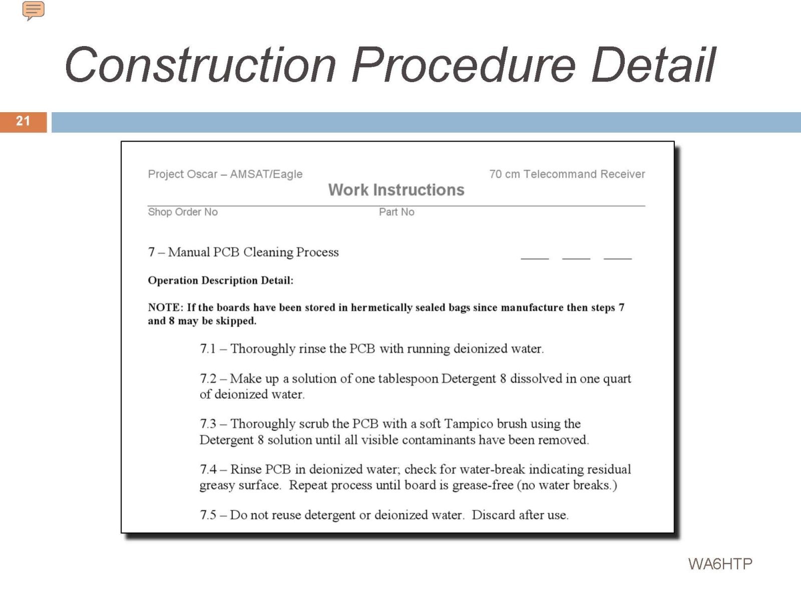
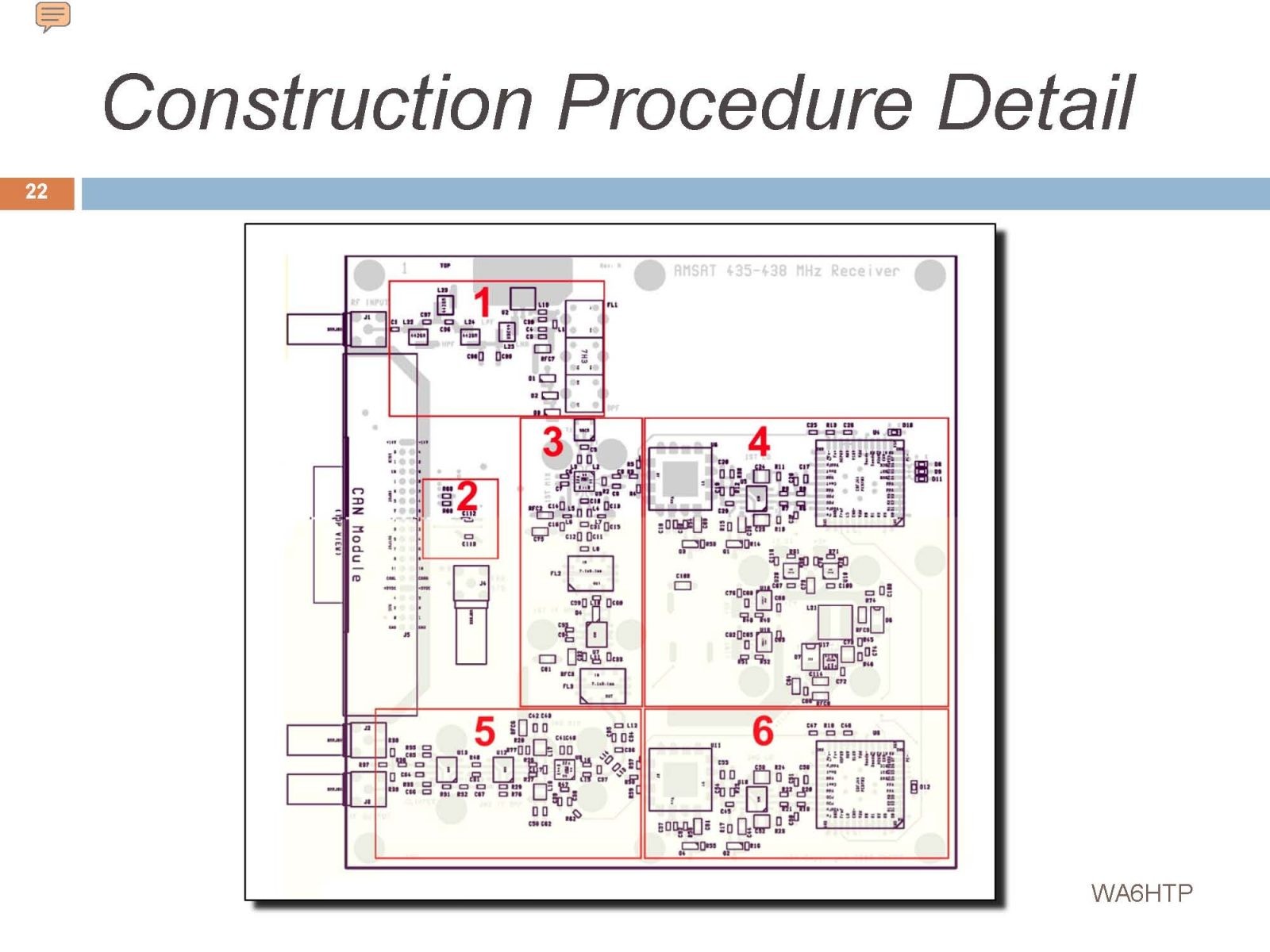
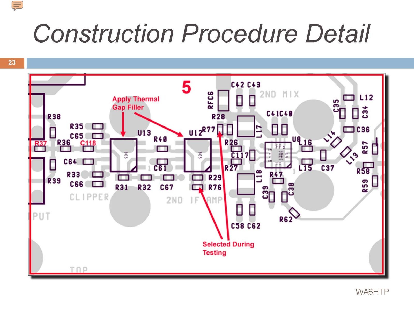
Each numbered section pointed to a detailed procedure for that section.
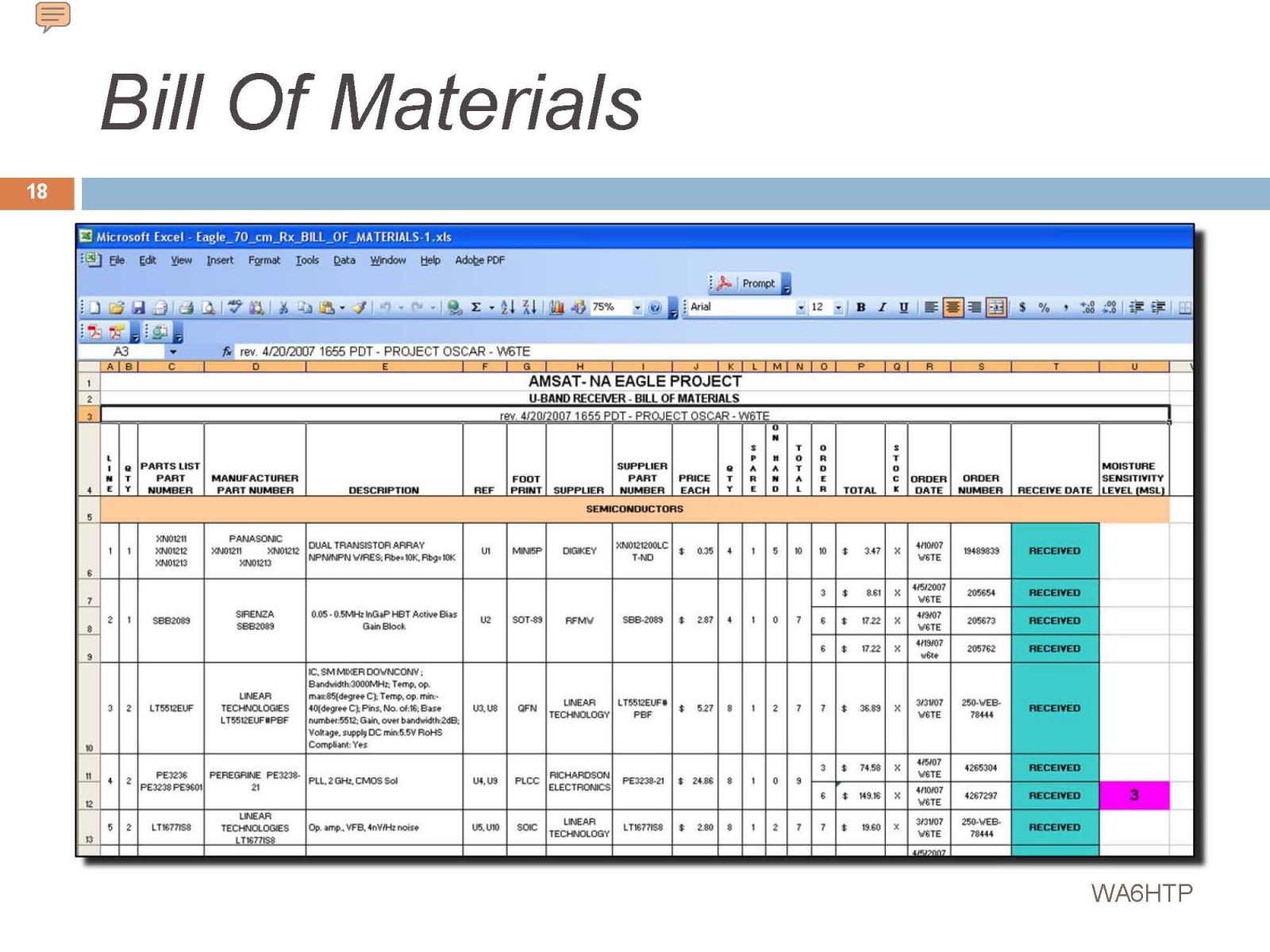
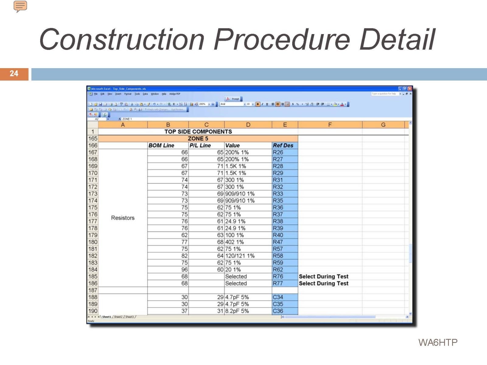
This spreadsheet ties the Bill of Materials, to the Parts List and the Reference Designator for each part on the circuit board.
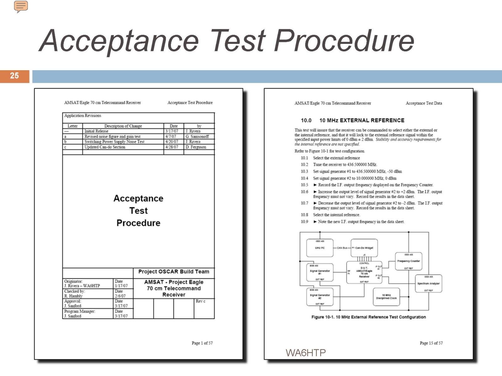
Conducting an Acceptance Test is the only way to insure that the item that you have constructed actually meets all of the requirements. If its done properly it will thoroughly test every aspect of the device in an unambiguous way. My ATP filled another large binder.
After a great deal of preparatory work, we are almost ready to get started…
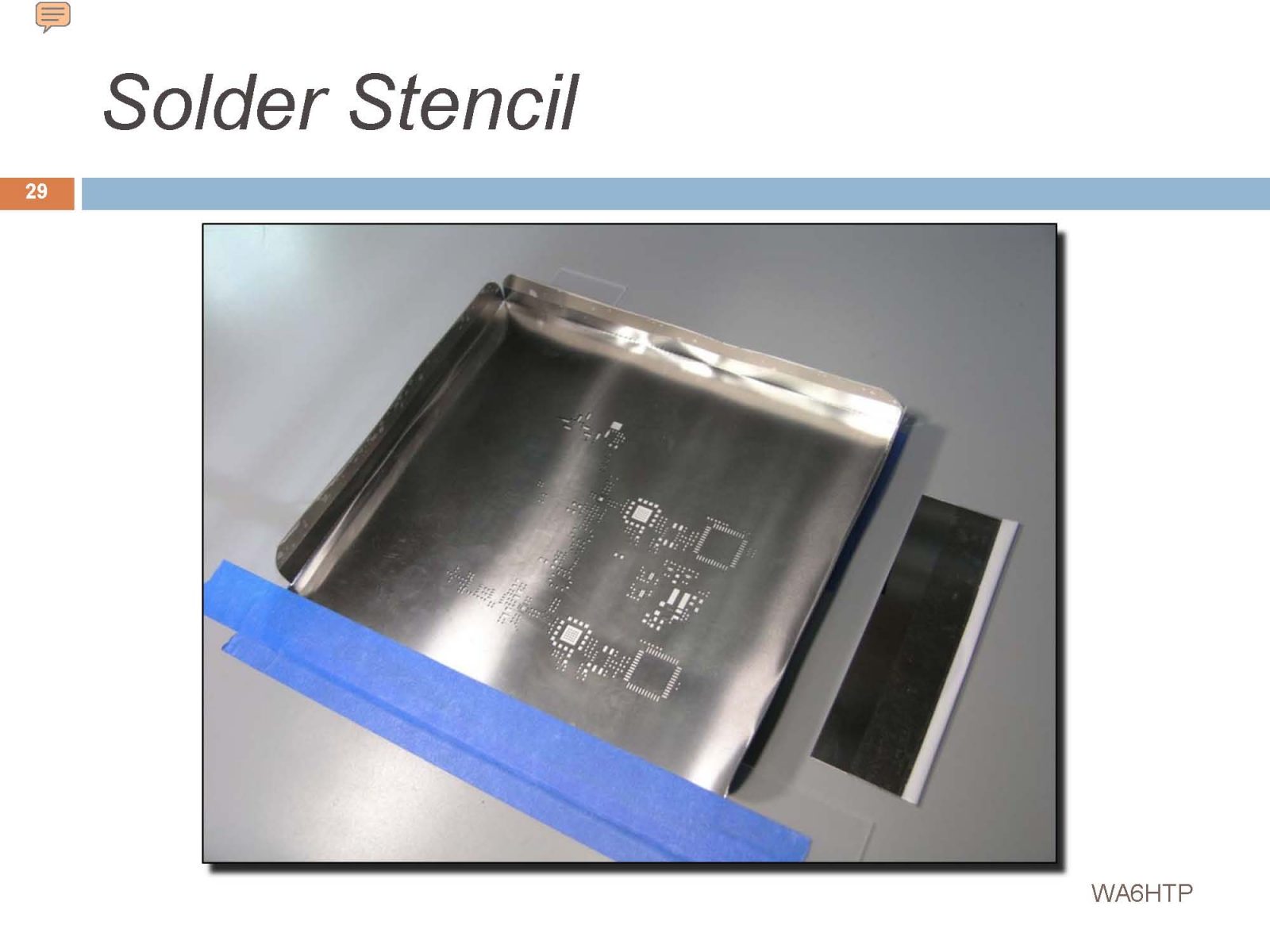
In reflow soldering the solder is a paste and is squeegeed onto the PCB through a very thin stainless steel mask.
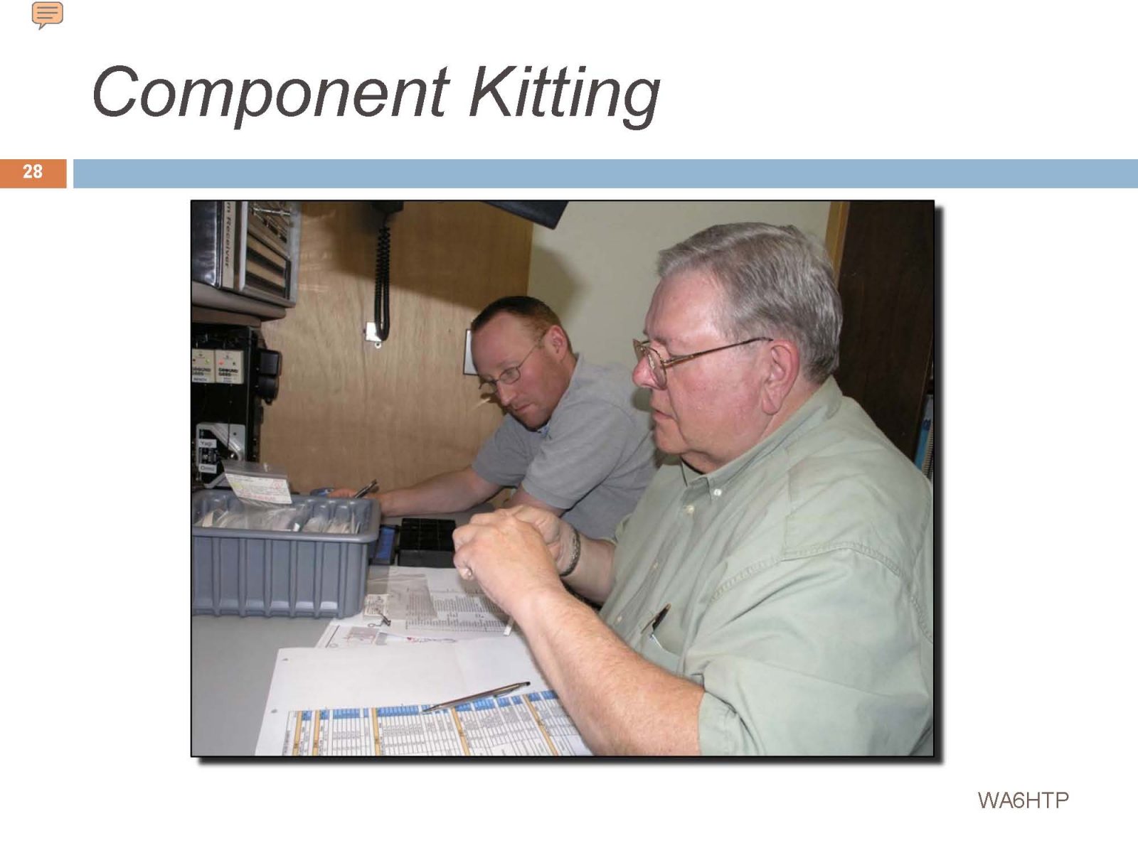
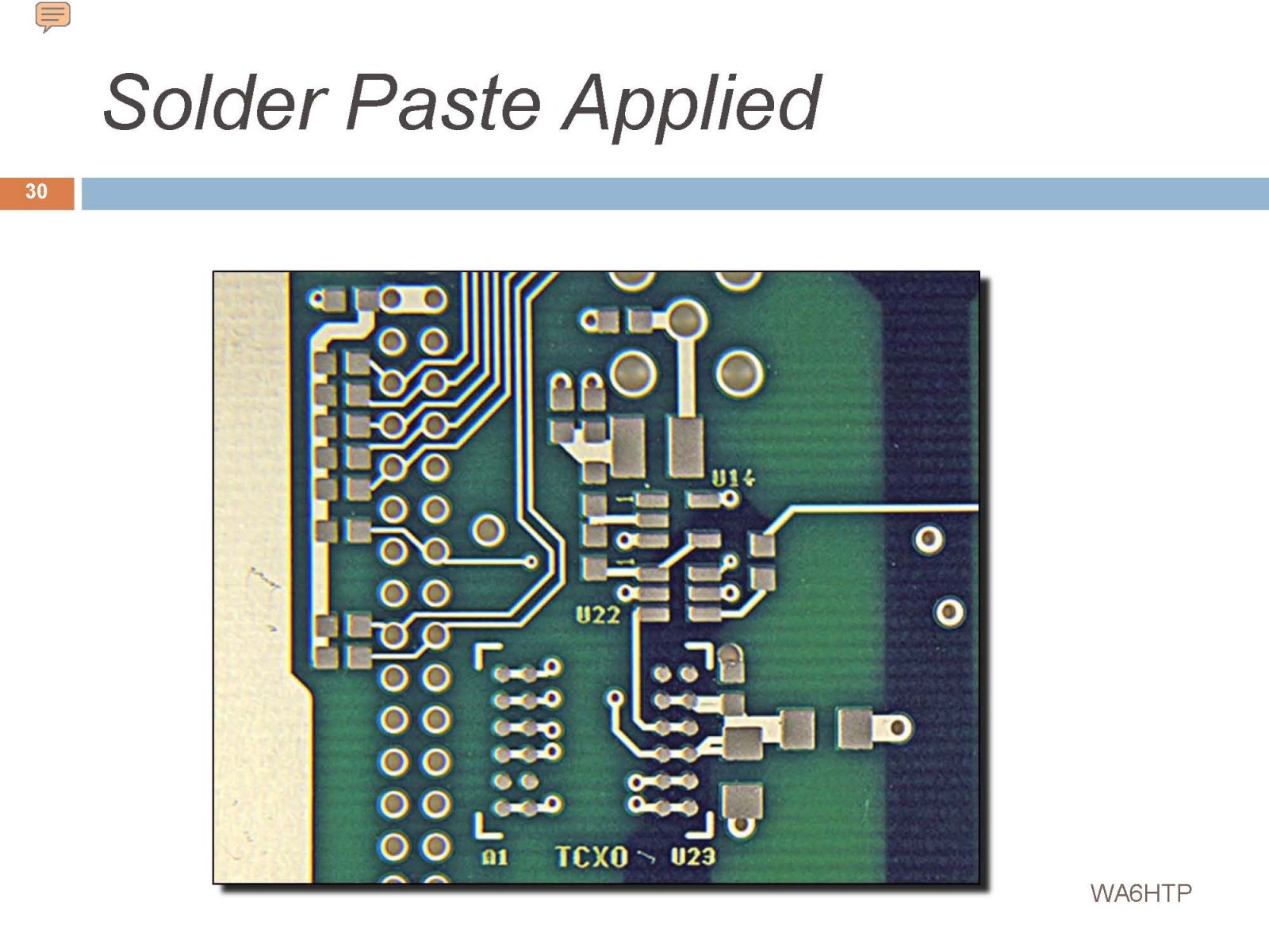
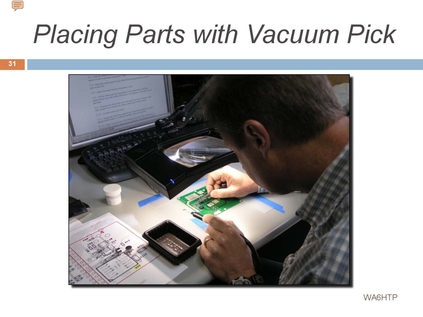
The gray dots are pads of solder paste which is a mix of microscopic solder balls and flux. The individual components are placed using vacuum tweezers. In a production environment a pick and place machine automates this step.
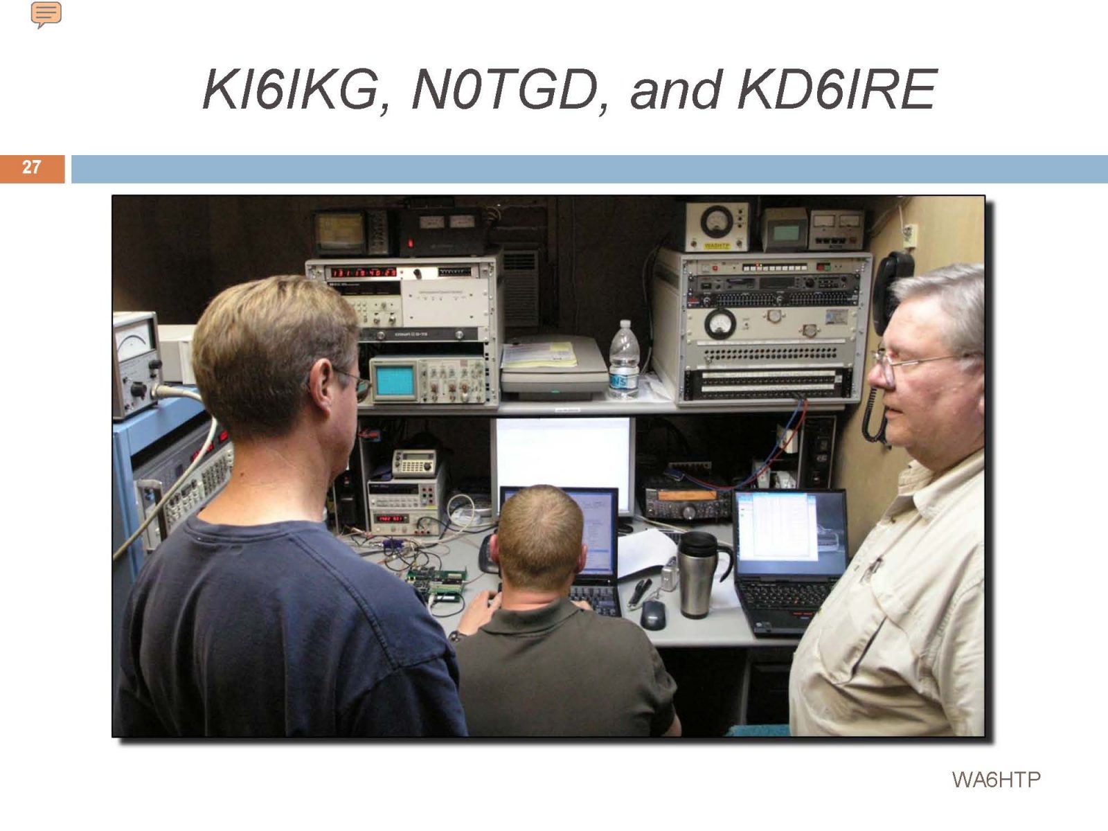
Greg, Hard at work with vacuum tweezers…
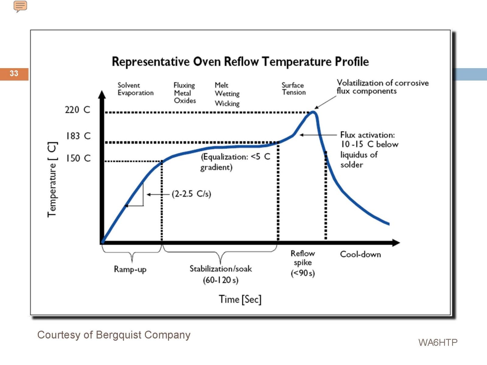
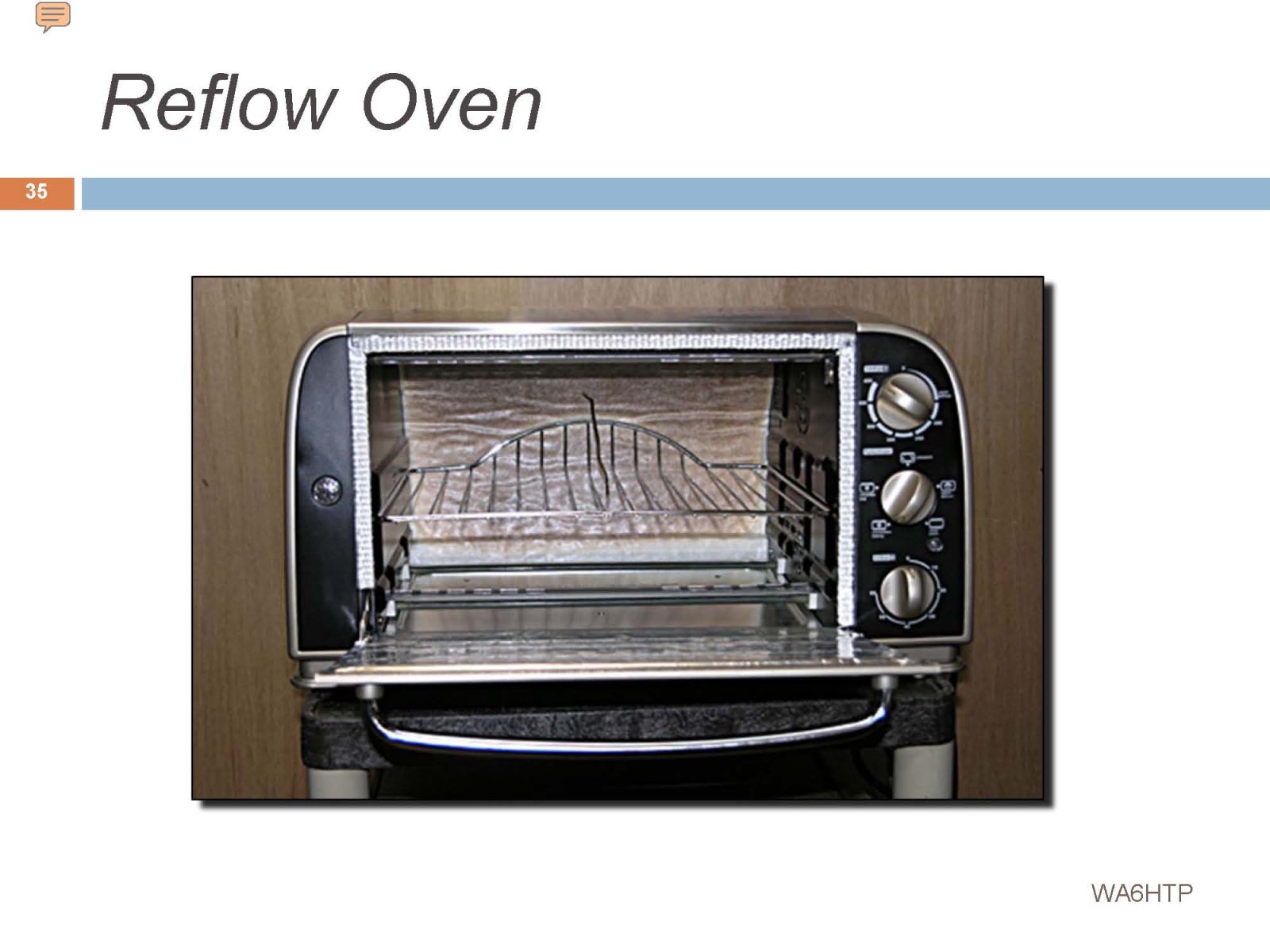
This was actually a very capable reflow oven for small prototype jobs. We learned a lot! The temperature profile is on the next page. Temperatures and timing are critical.
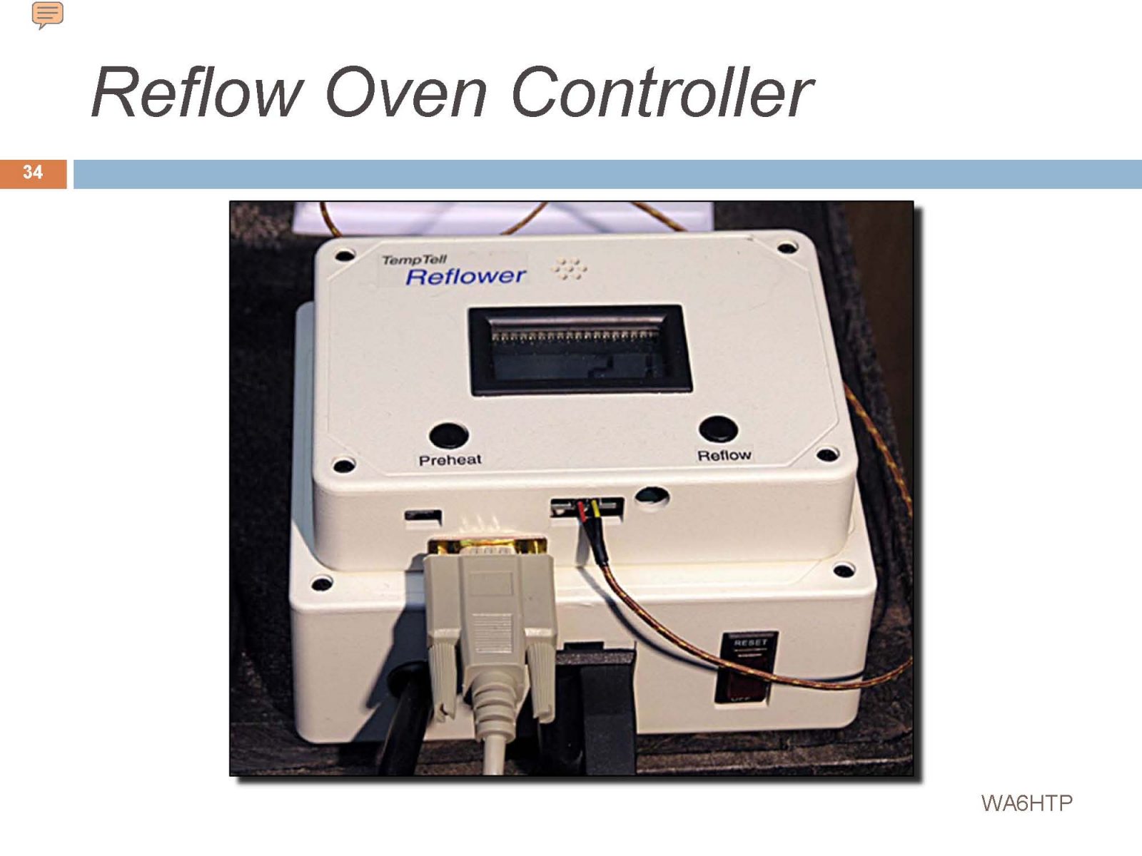
This reasonably-priced controller managed the temperature and timing profile for the modified toaster oven. I added a LabVIEW application to monitor and document the process.
Well, here it is… There is a temperature probe that sticks in from the rear, and there may have been a few other minor modifications, but it’s basically a toaster oven…
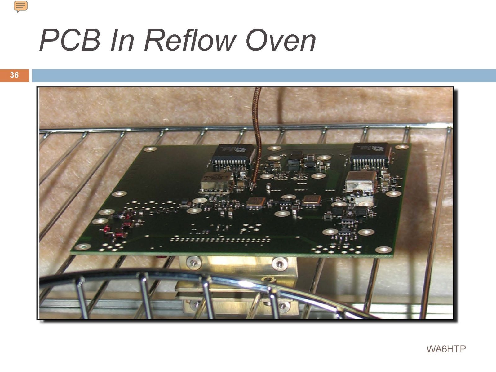
This receiver had components on both sides of the board. The solder p[paste will hold those parts in place even thought they are upside down. The thermocouple can be seen touching a major component on the board to monitor temperature.
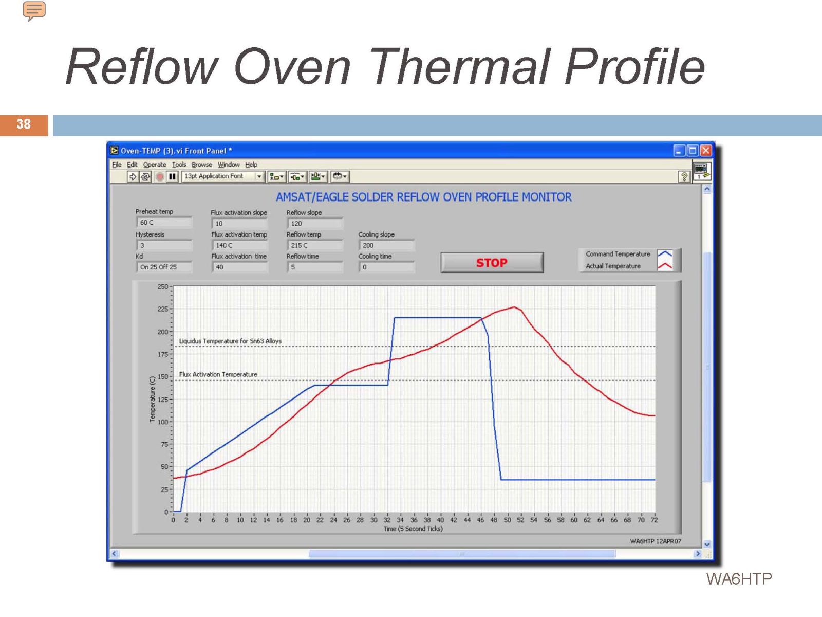
I whipped up this LabVIEW monitor to control, monitor, and record the temperature profile. The blue line is the ideal temperature profile and the red line is the actual result. All temperature and timing parameters were set with this application and passed to the controller.
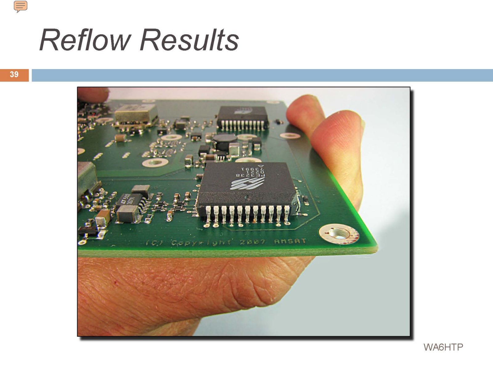
Here’s Prototype #1, Ready for Testing. There were components on both sides of this PCB. They manage to stay in place through the soldering process…
The entire Eagle project ran out of steam at the Telecommand Receiver prototype testing phase. AMSAT leadership seemed to come to a complete stop. Our initial testing turned up a series of unfortunate problems with the CAD-Do module that should have been caught much earlier.
You’ll see our test results in the following slides…
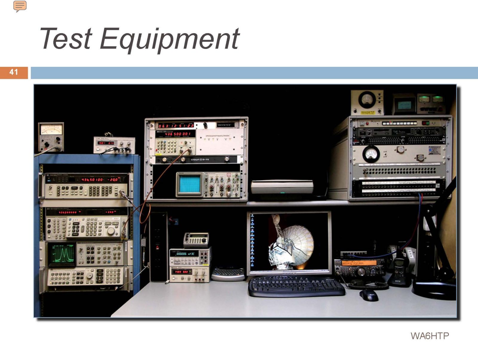
Here’s my collection of used HP test equipment. Everything was in good shape, and it all still works today!
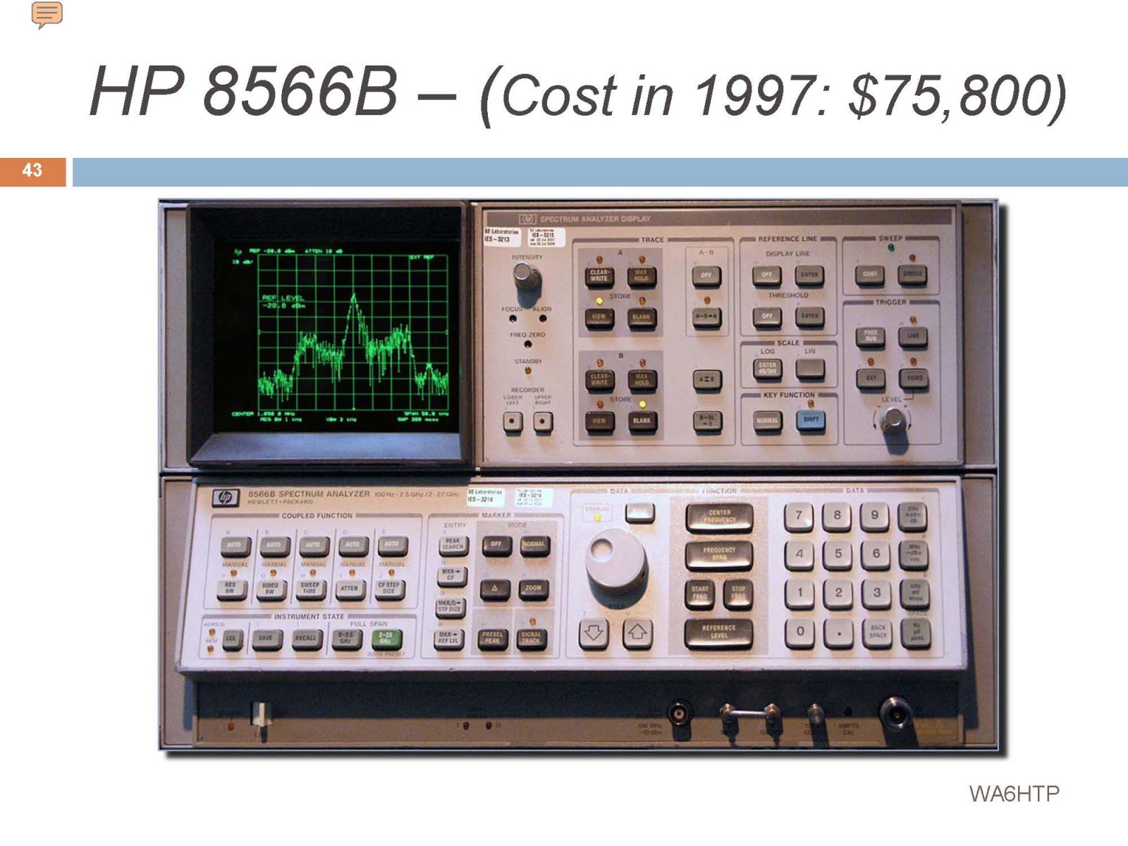
My pride an joy – an HP 8566B Spectrum Analyzer. It sold new for around $85,000. I bought it used for around $3000. Now, I can’t find anyone to give it to. That’s progress…
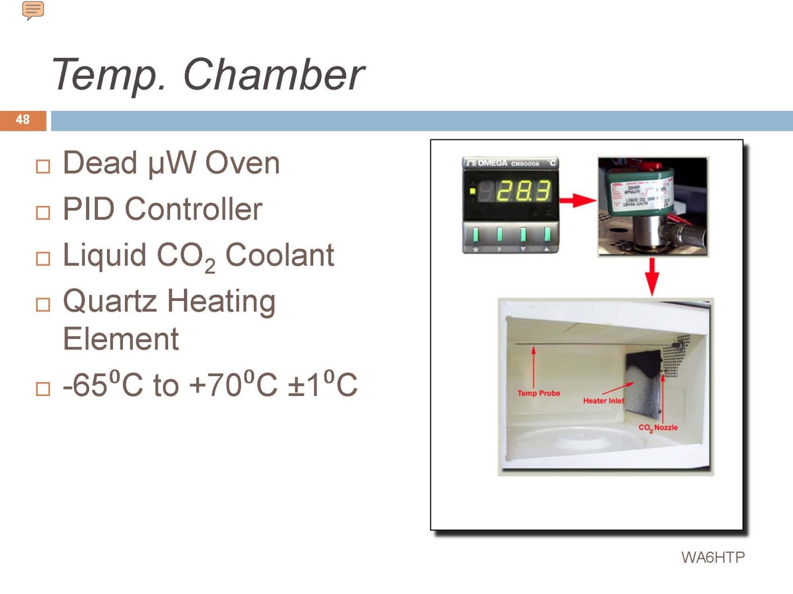
This is my home made temperature chamber. It’s made from a $5 burned out microwave oven. I ripped out the magnetron and installed a quartz bathroom heater element. Cooling is supplied by a tank of liquid CO2 via a very fine nozzle. The nozzle if fed with a cryogenic solenoid valve, and the whole thing is controlled with an industrial PID controller. It worked very well! Just one problem – the CO2 displaces oxygen in the area and it can kill you with no warning! Don’t try this at home!!
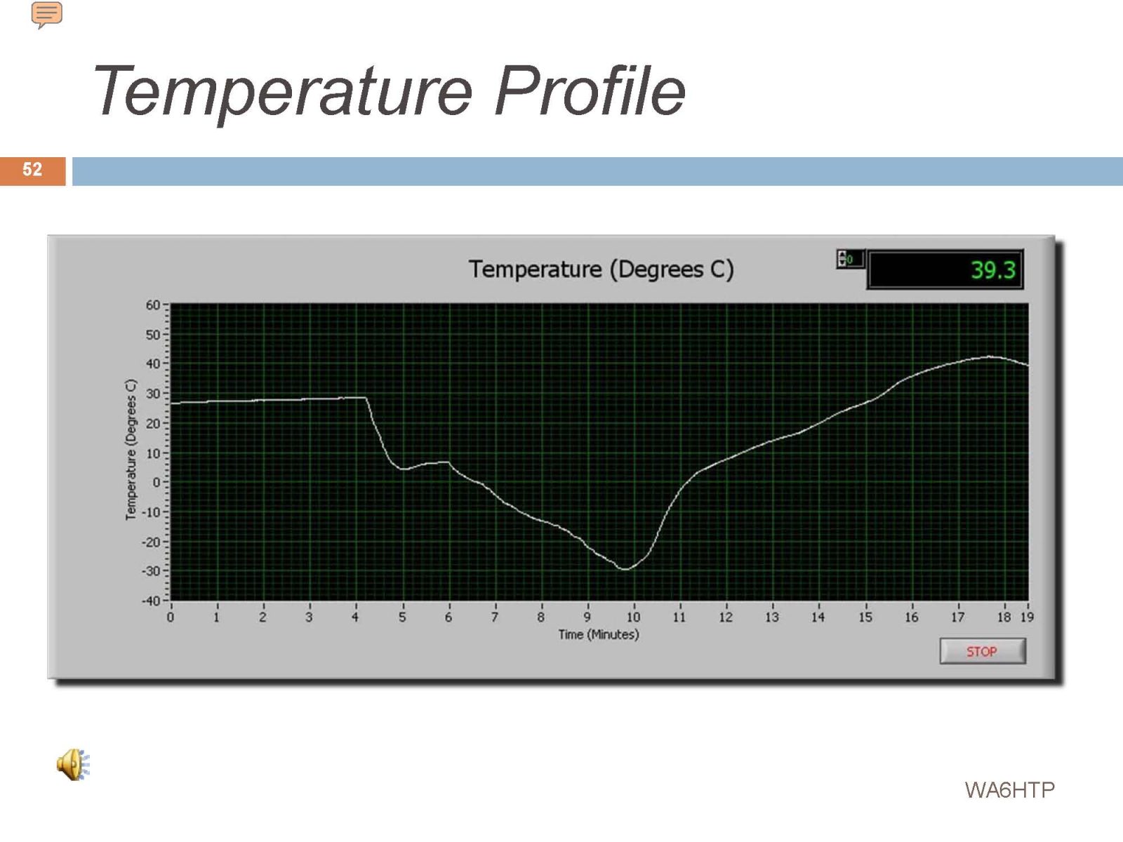
Here’s a thermal run while looking at the Local Oscillator frequency. The run started at a room temperature of about +28C. We then dropped to approximately +15C, leveled off briefly, and then went down to -30C. At that point we started back up, using the bathroom quartz heating element, and over the next seven or eight minutes, reached a temperature of +40C. This is all done by pulsing the CO2 and heating elements on and off.
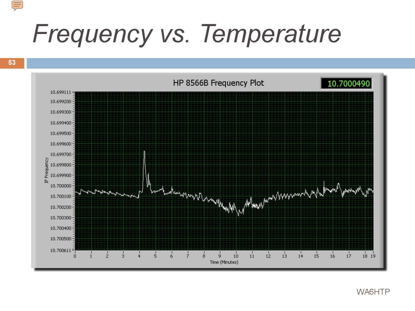
Here’s the local oscillator response to the temperature run. That spike might have been caused by the chamber temperature dropping rapidly in response to a blast of CO2 that was not registered by the temperature probe. The crystal would have much less thermal inertia than the probee and would respond much faster…
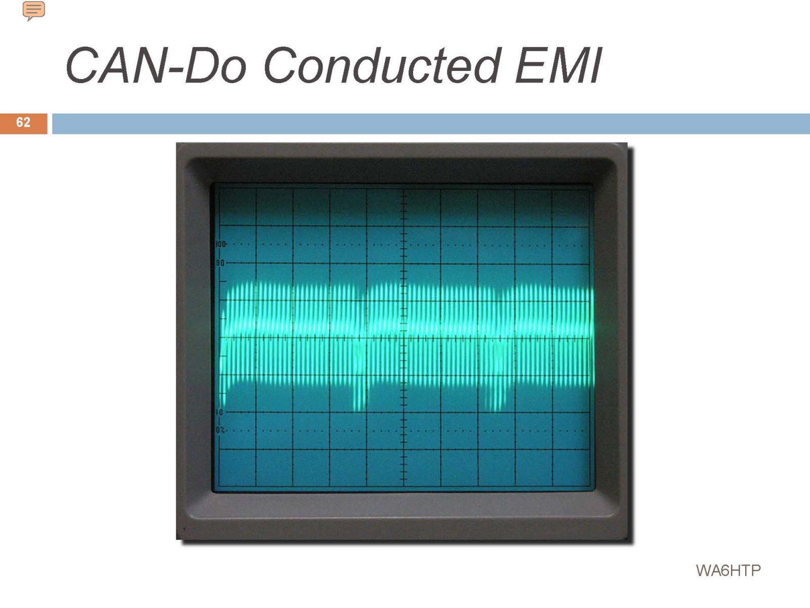
The on-board switching supply created a great deal of EMI. The toroid (lower right) was the main source…
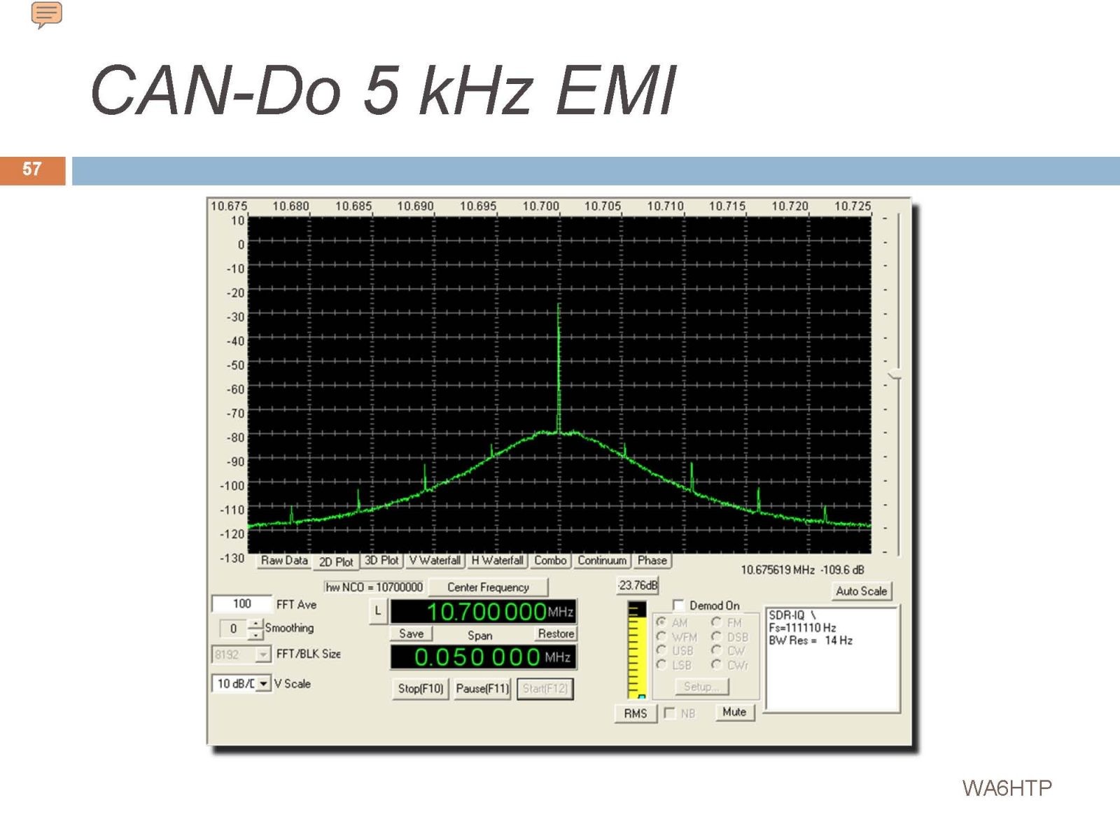
The switching supply created a spike at 5 kHz intervals. It’s unfortunate that this was not caught during CAN-Do development. The CAN-Do modules were already in production by the time this problem was discovered. This is what happens when you skimp on initial planning and thorough peer review.
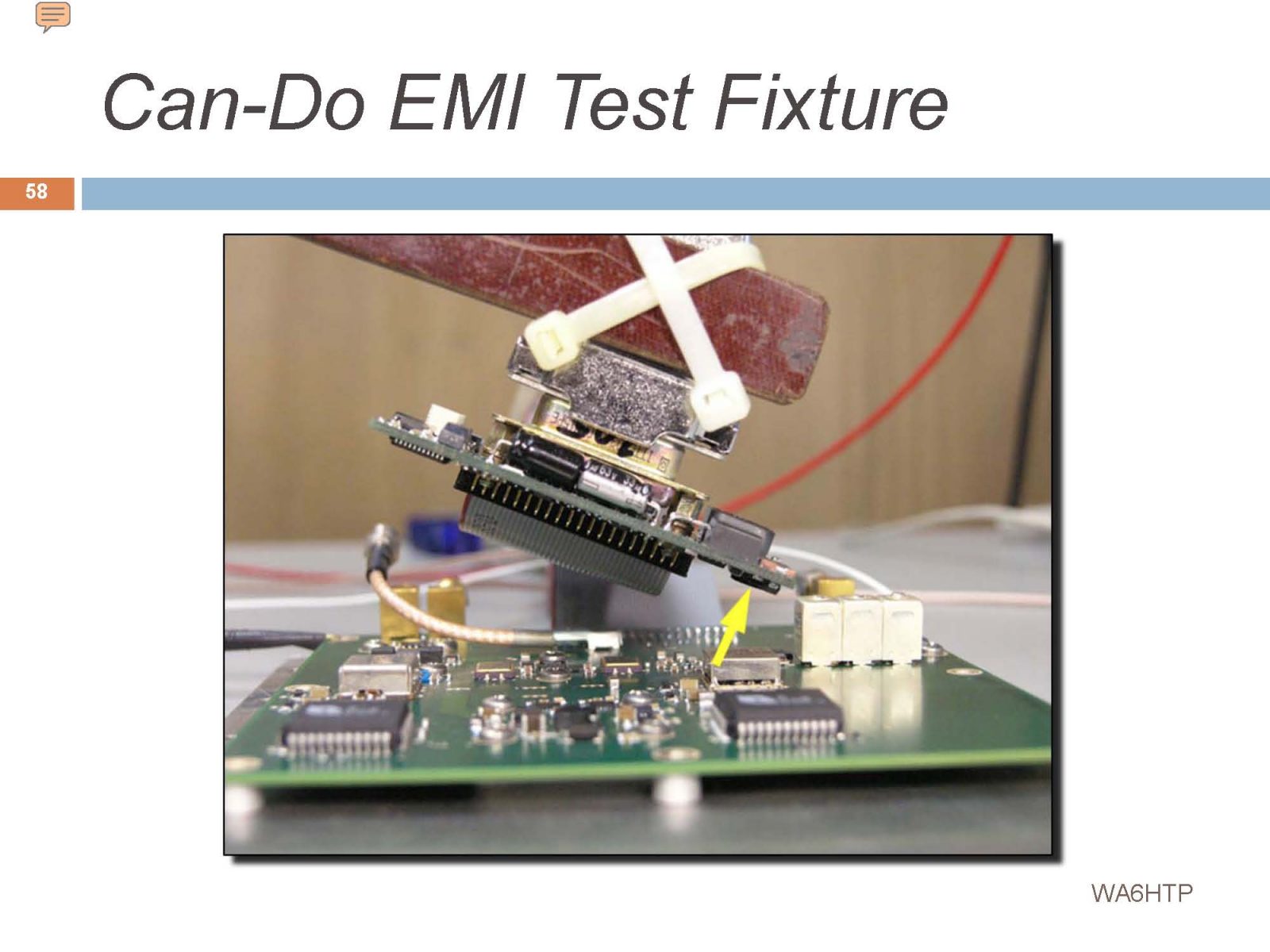
The CAN-Do module is being held above the receiver to characterize radiated EMI to the receiver.
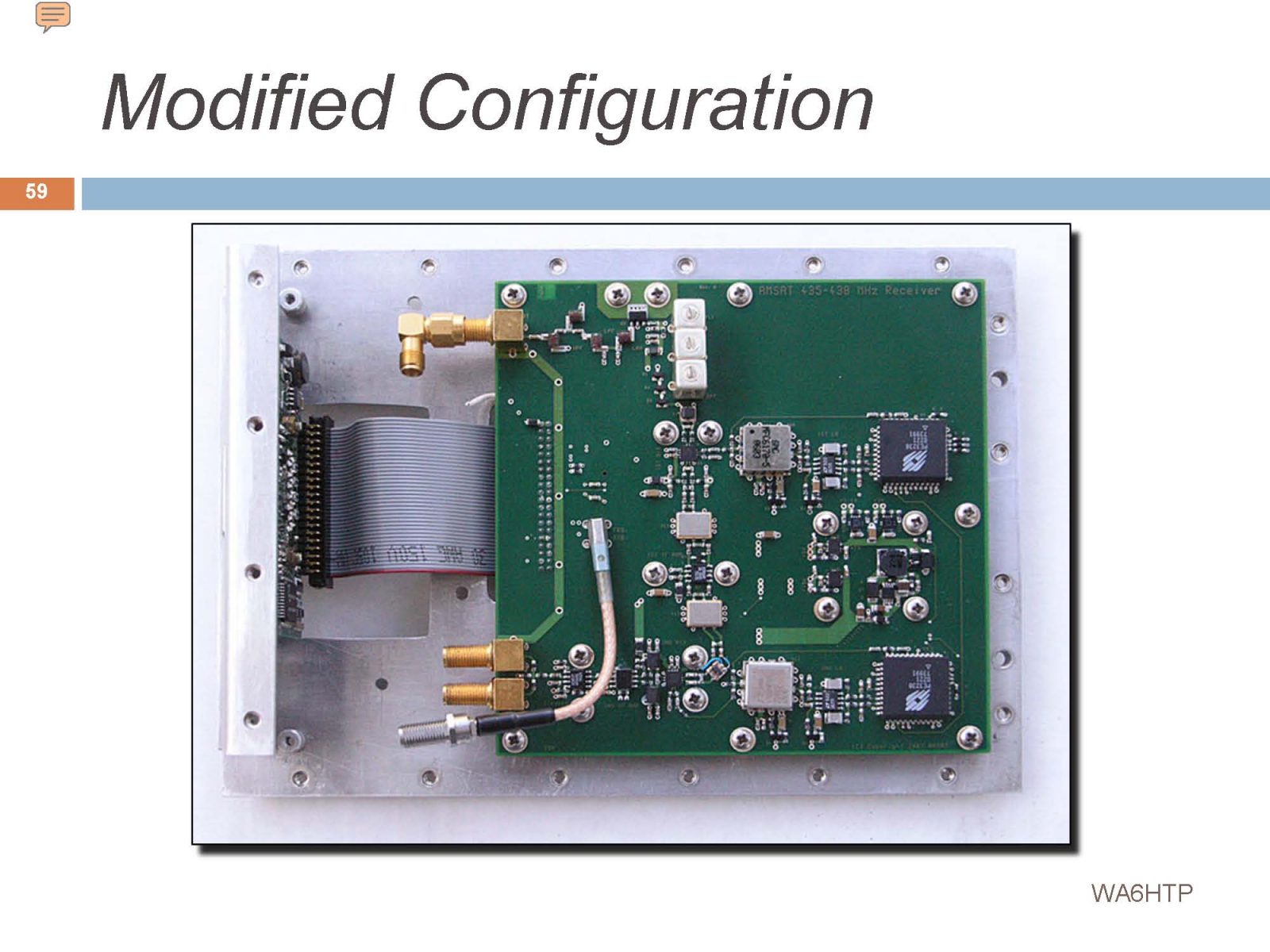
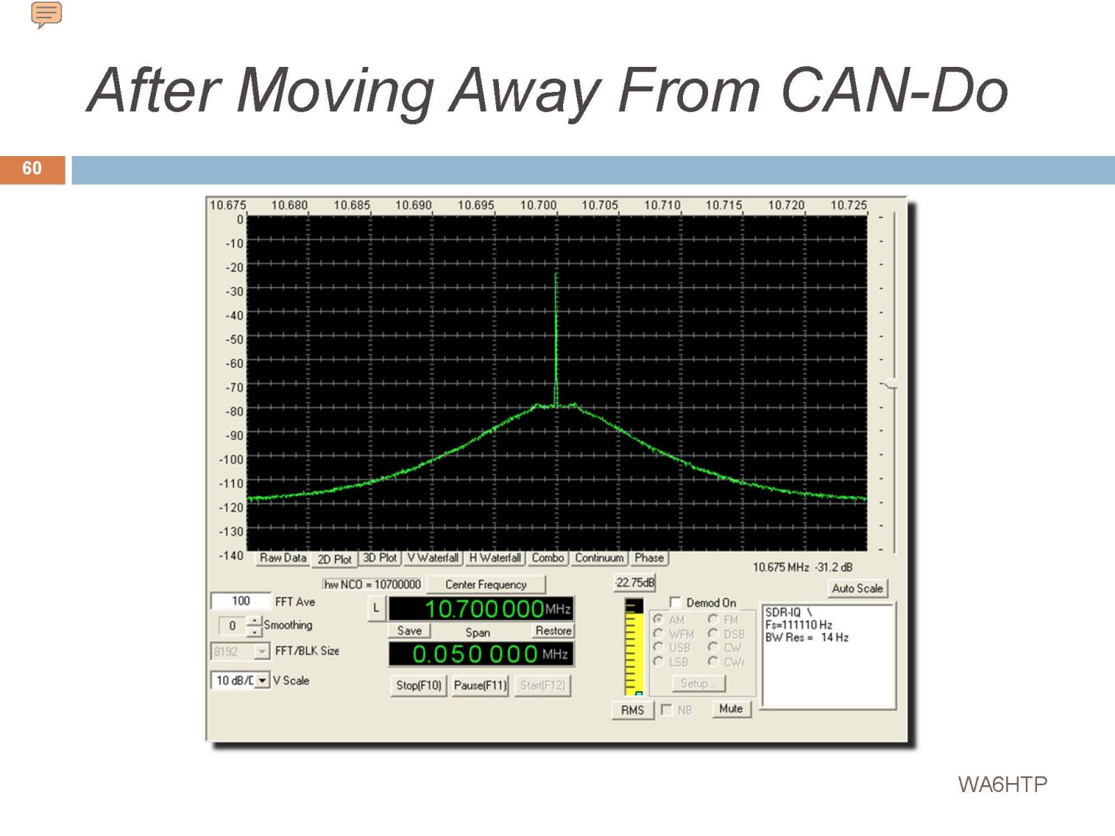
The receiver was physically moved away from the CAN-Do module by installing a ribbon cable between the two and sliding the receiver as far away as possible. It may have reduced radiated EMI but would have no impact on conducted EMI.
That resulted in an improvement in the radiated EMI (The spikes are gone).
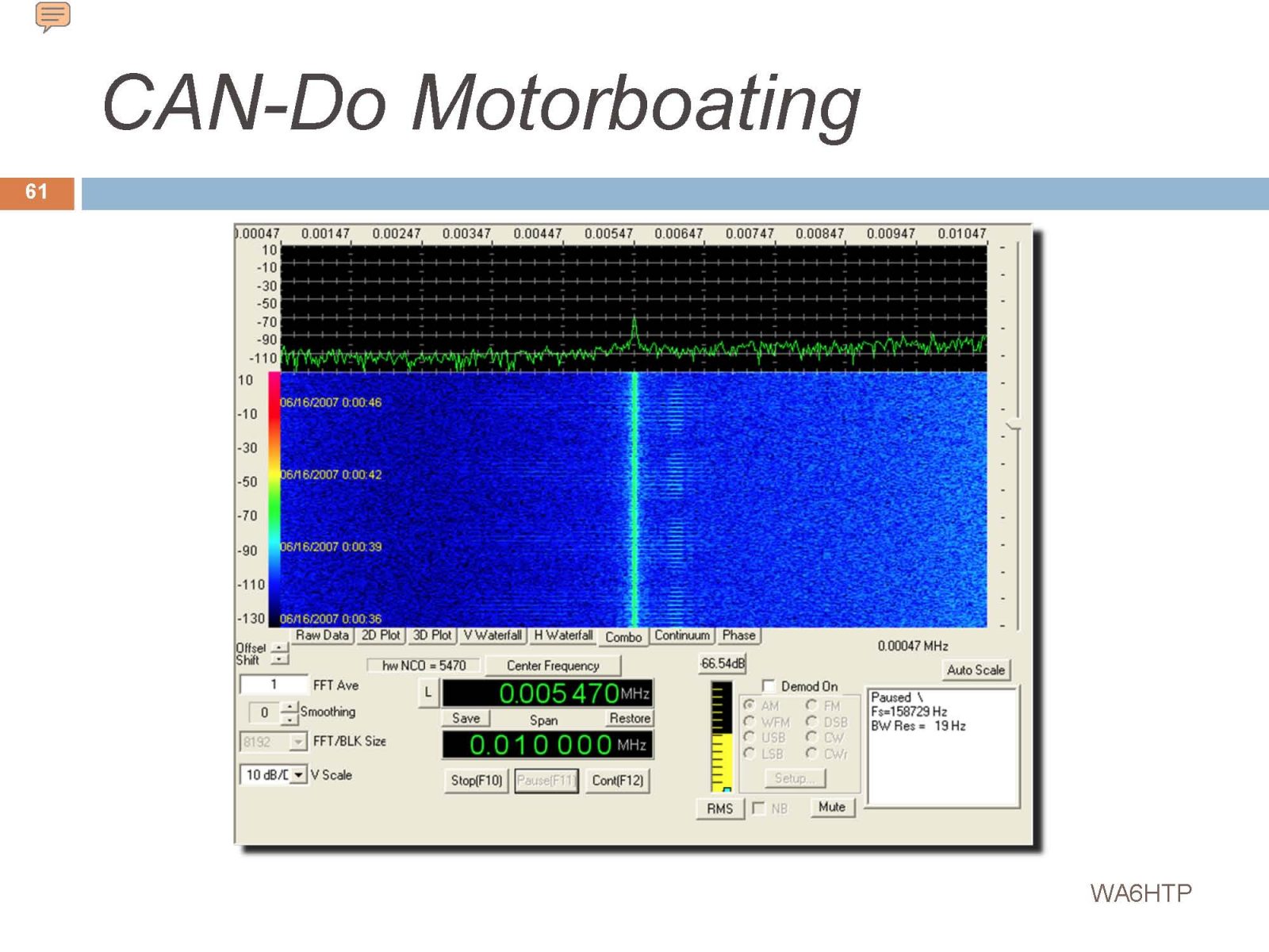
CAN-Do Motorboating. More unexpected behavior…
This noise was propagated into the receiver via the interconnecting wiring. By now it was clear that the CAN-Do module at the very heart of the spacecraft design had major problems…
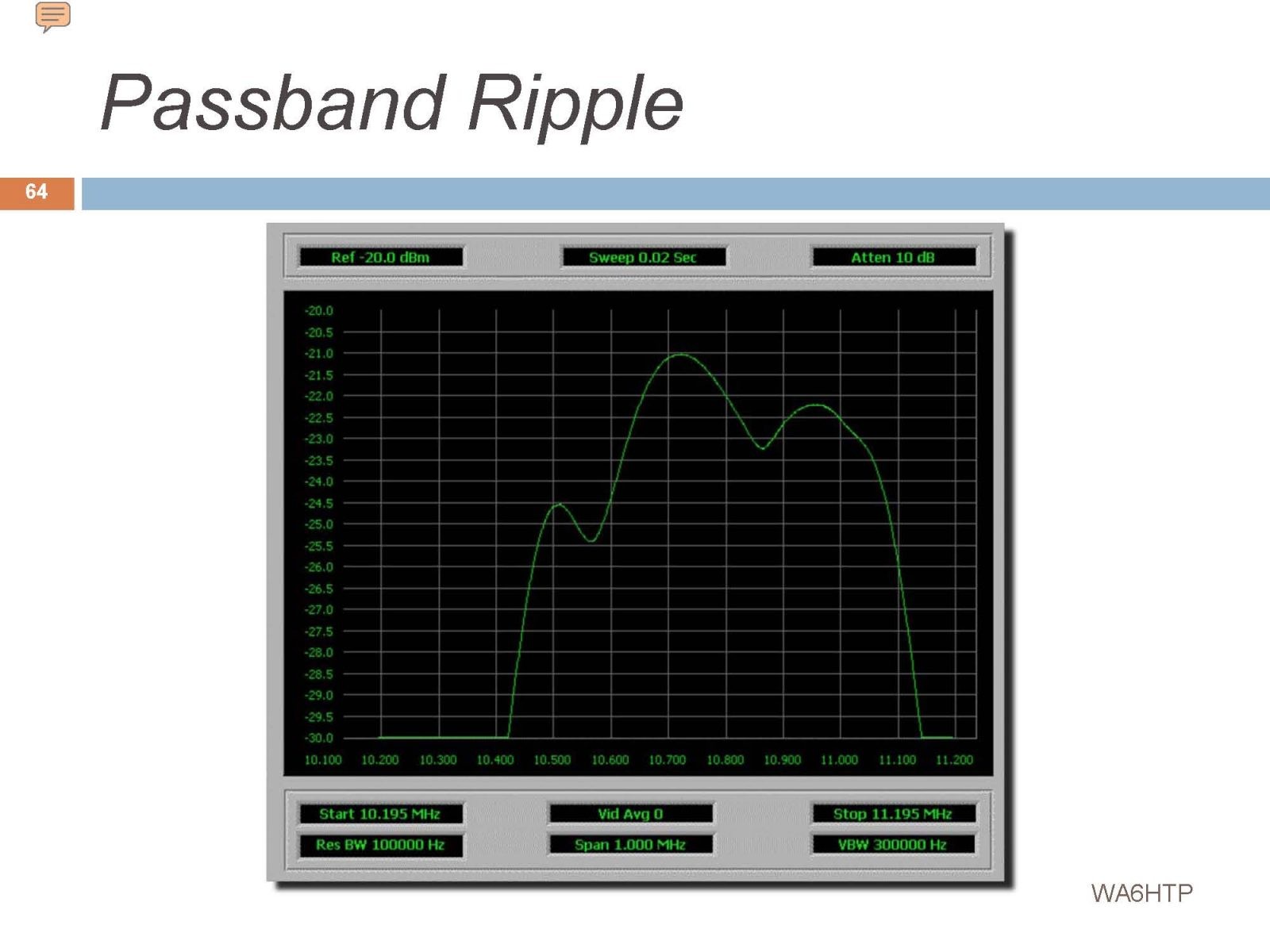
Testing also revealed that the receiver had its own share of problems, but at least it was in the prototype phase, so this was not unexpected. That’s why you build a prototype and rigorously test it.
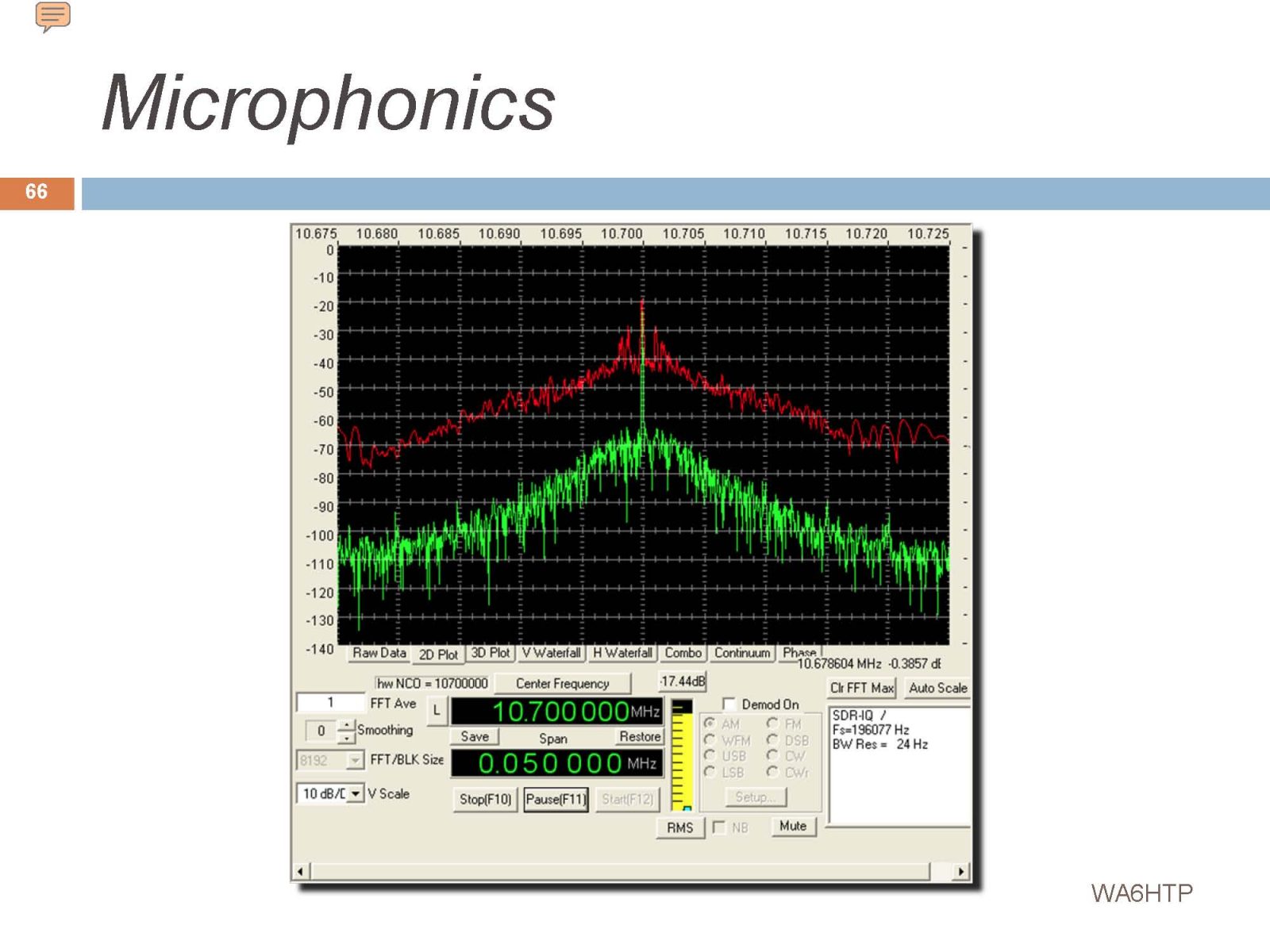
Ceramic chip capacitors are notorious for causing microphonics – the capacitance can change when they are exposed to shock or vibration. This may not have been a problem in space, but it was noted.
The result of a slight tap with a plastic rod.
We only made it part way through the first phase of the Telecommand Receiver project when the entire satellite program fell apart. I’m now exactly sure what happened to cause the project to collapse…