Helicycle Electrical Construction
The electrical system and avionics are left almost completely to the discretion of the builder. I discarded almost all of the inexpensive components and replaced them with high-quality aerospace components. I also vastly increased the capability of the systems – a 55-Amp charging system, a Rotor RPM Alarm, a Crew Alerting System, and many other enhancements. This portion of the project probably consumed half of the total build time…
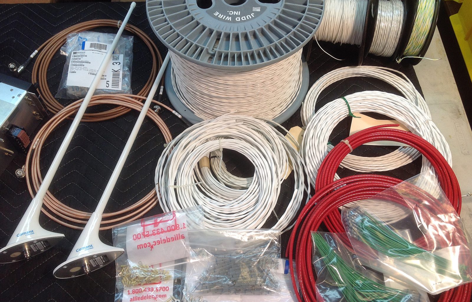
Everything starts with quality aerospace wire and cable and proper shielding. The Helicycle engine is controlled by an electronic governor. If it loses power or his hit with either conducted or radiated EMI from the VHF Transceiver, the engine could shut down in flight…
The items on this workbench represent a large portion of the total electrical and avionics wiring to and from sensors, actuators., and exterior lighting.
Not shown is the high-current DC power circuitry…
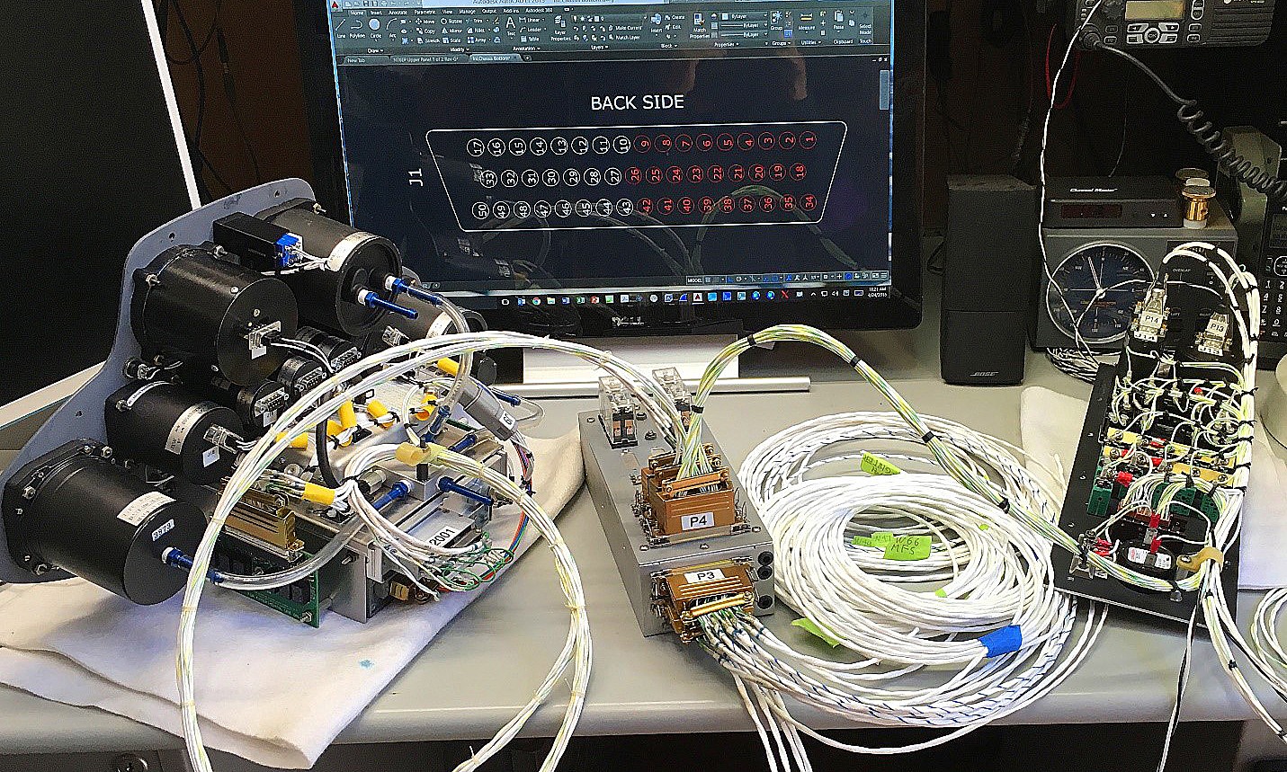
The Upper Instrument Panel contains almost all of the flight and engine instruments, my custom Crew Alerting System (CAS) logic board, and my custom Rotor RPM Alarm processor board.
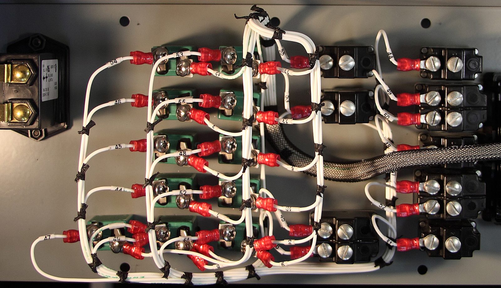
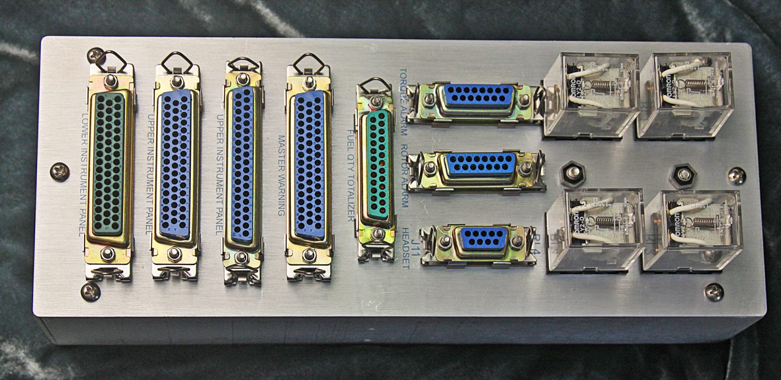
This is my custom Interface Chassis. It ties all of the various subsystems together…
This is my custom Interface Chassis. It ties all of the various subsystems together…
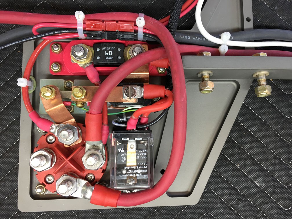
This is a closeup of some of the high-current DC wiring. The starter on the turbine engine drew 1200 Amps of surge current. Heavy wire was called for.
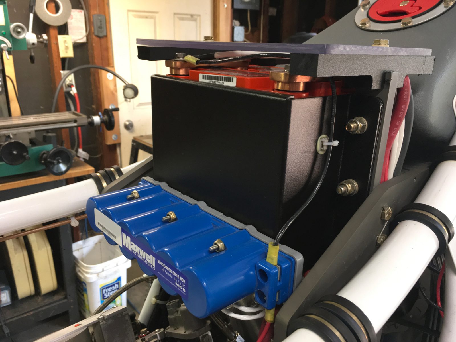
These components are mounted on a plate that I CNC machined and had hard coat anodized. That was also a fun learning experience…
This is the top of that same assembly. All the heavy gray pieces are CNC-Machined and had-coat anodized. The frame slopes down and away which made for some tricky angles. I’m using two AGM batteries to handle the 1200-Amp starter current surge. During an engine start, the essential DC bus is switched to the blue Ultra-Capacitor which is isolated from the battery during a start.
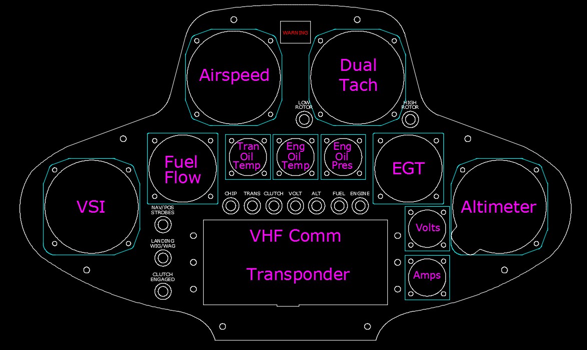
I did the electrical and mechanical design using AutoCAD. This is the design for my second generation Upper Instrument panel. All stock factory instruments were replaced with high-quality custom instruments that I designed and hd manufactured for the helicycle community.
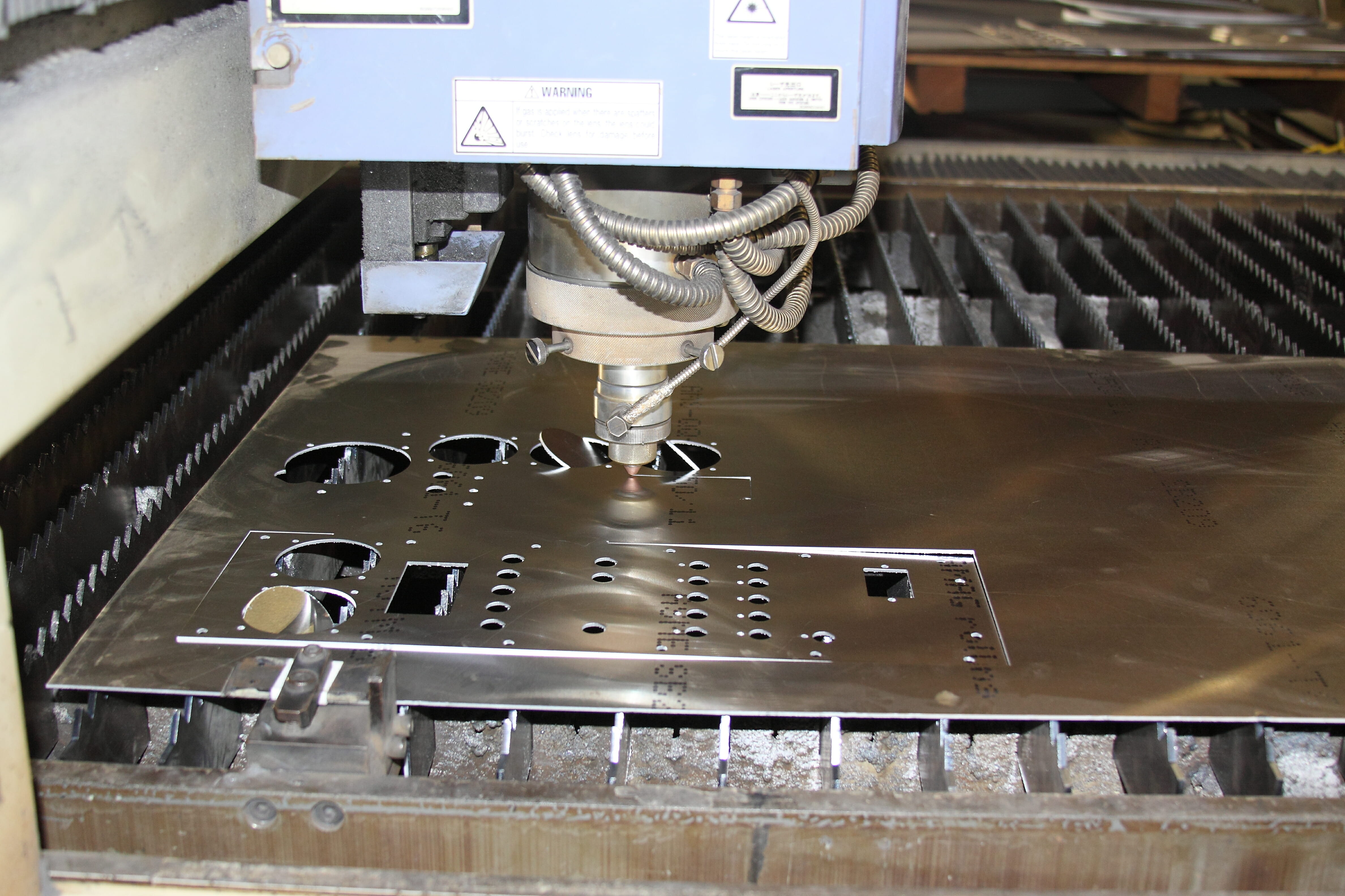
I had my first set of panels was cut with this laser, working off of my AutoCAD drawings…
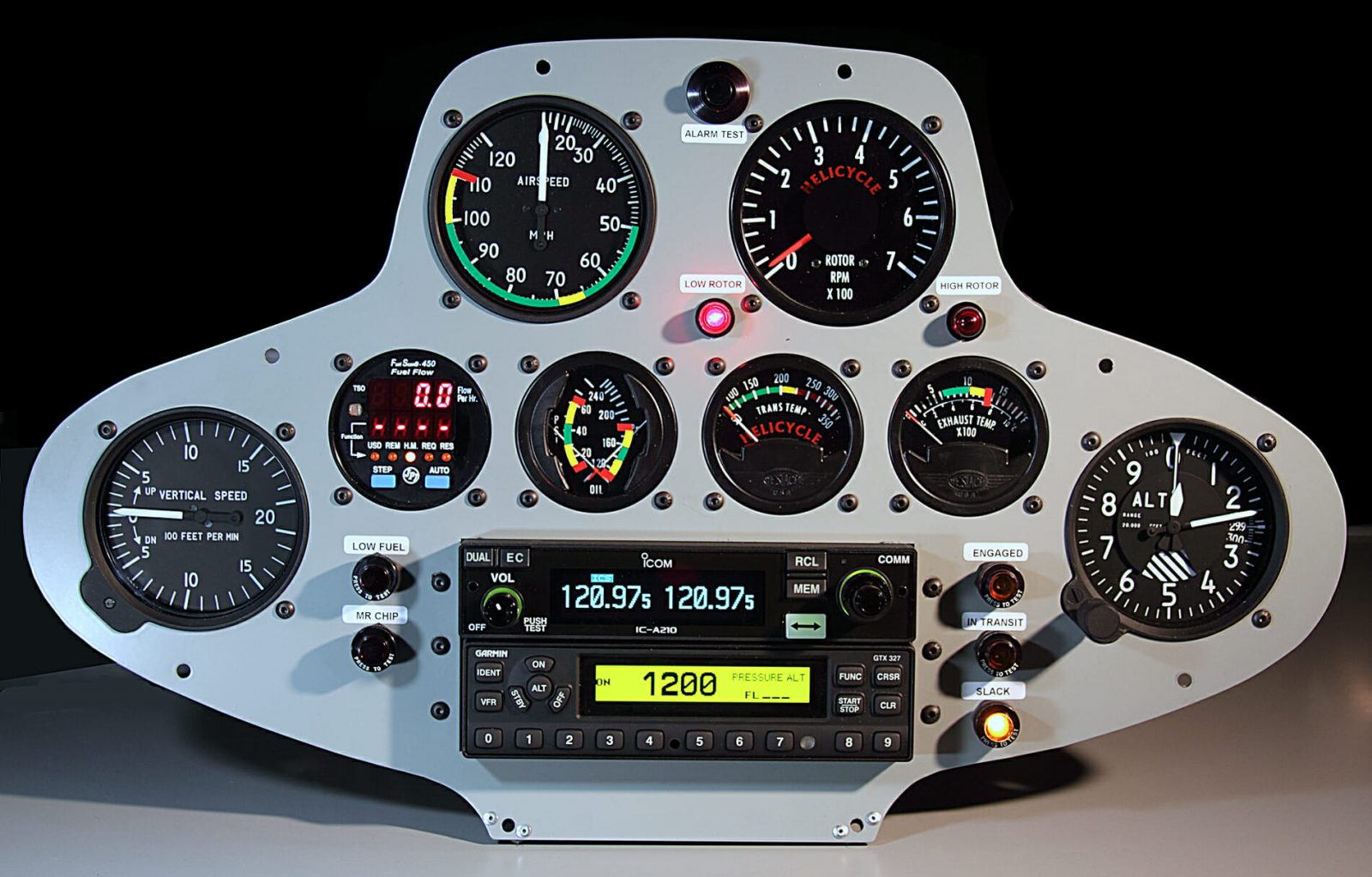
This is my first generation Upper Instrument Panel. It used all of the stock factory instruments – #2,3, and 4 in the middle row, and the Rotor Tach in the upper right. My first custom instrument was an analog Fuel Flow indicator that took the place of #1 in the middle row. That configuration is what you see in all of my flying videos and pictures of the ship…
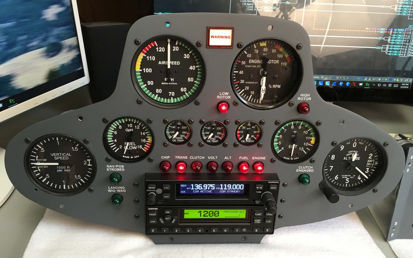
This is my second generation Upper Instrument Panel. It makes use of all of my custom-designed instruments and also my Crew Alerting System (CAS). As luck would have it, my eyesight started to deteriorate and I could no longer fly. I never had the opportunity to fly with my panel. Bummer!
This little slideshow is all I have to show for many months of hard work…
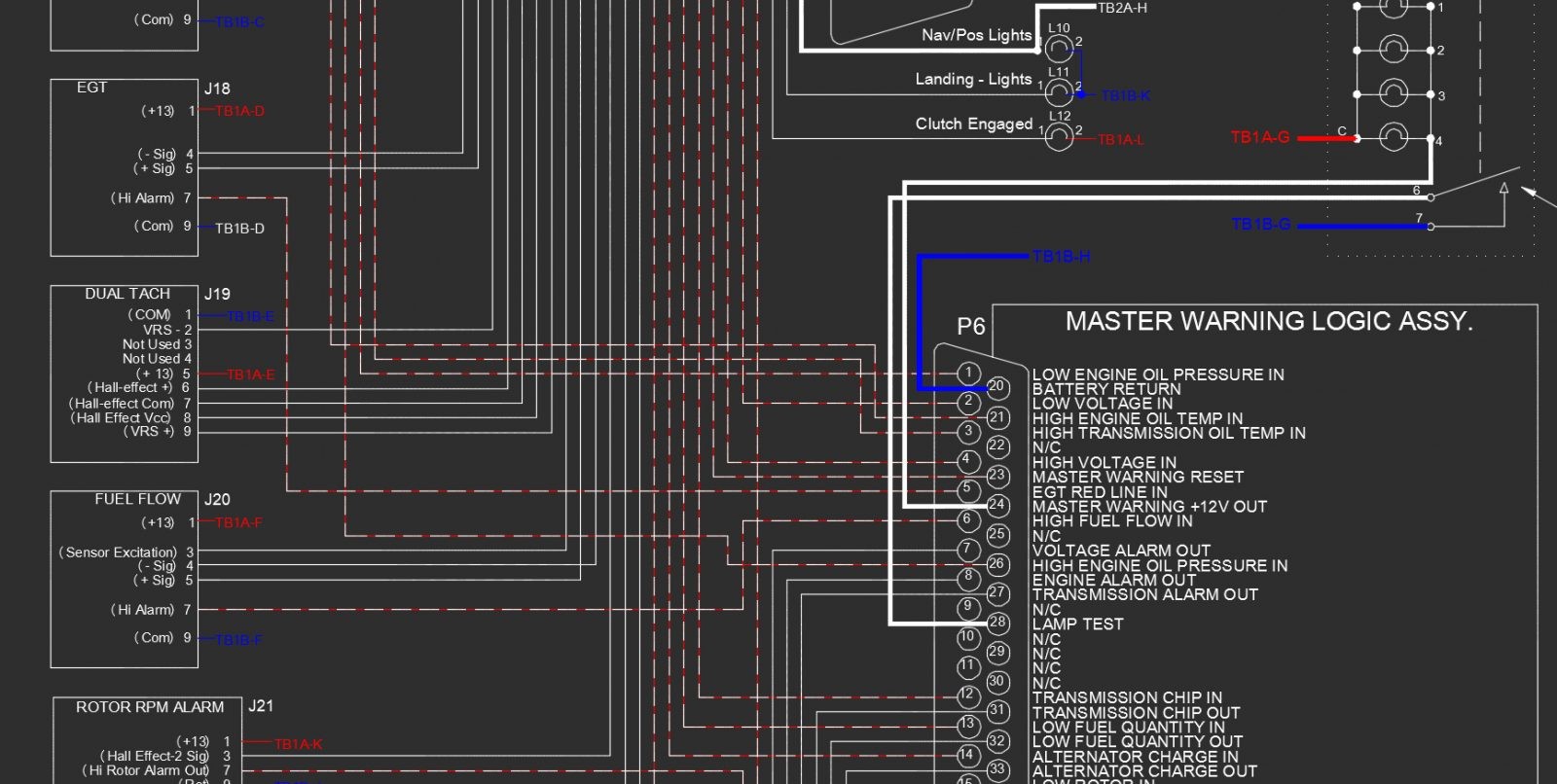
This is a portion of my Upper Instrument Panel wiring diagram. You can see that the Crew Alerting System (CAS) logic module is monitoring the Exhaust Gas Temperature (EGT), Fuel Flow, and the Rotor RPM Alarm. In all it is monitoring fifteen parameters…
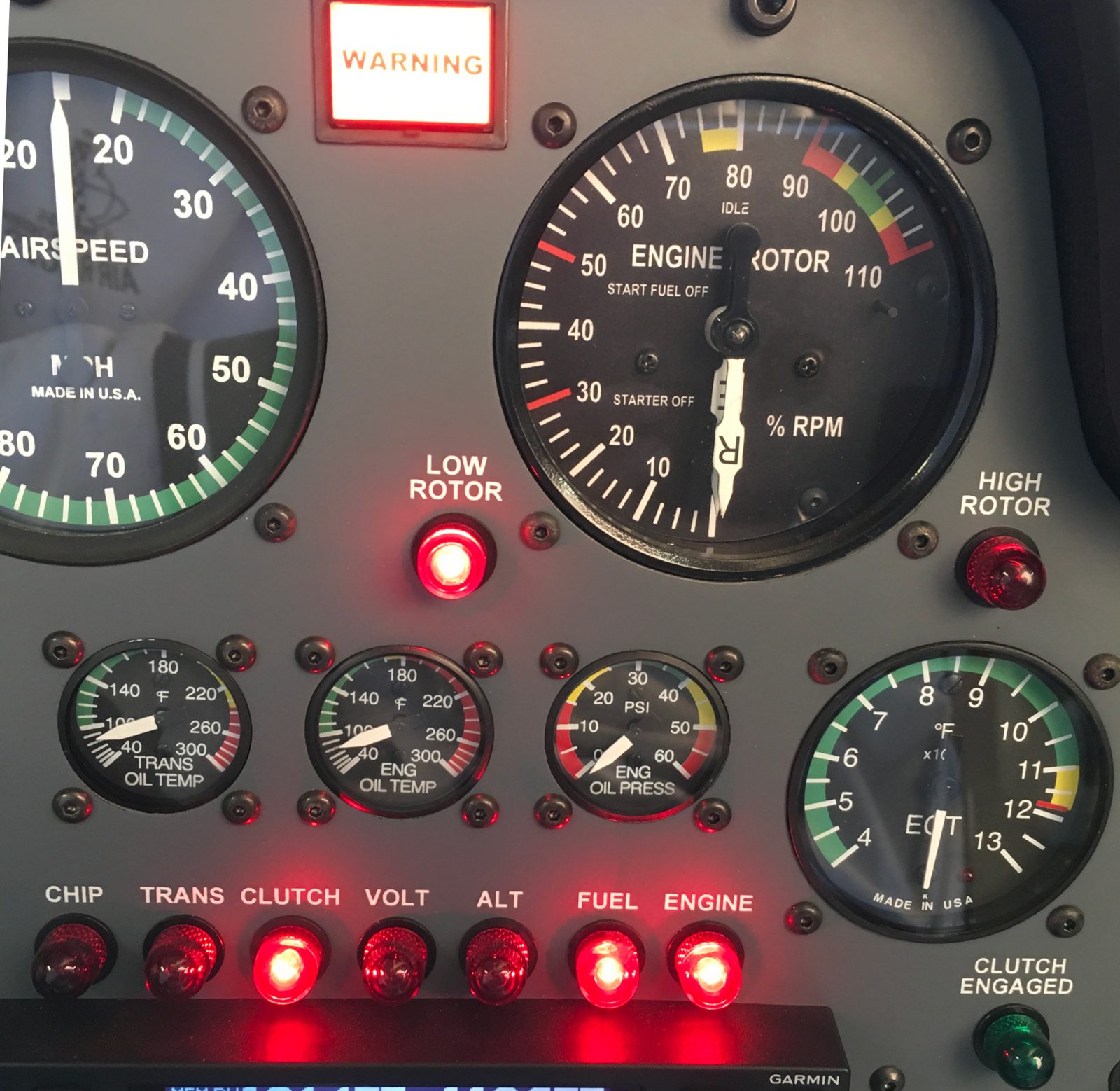
In this picture the CAS is showing multiple alarm conditions:
The Clutch is disengaged
Low Fuel Level
Low Engine Oil Pressure
Low Rotor RPM
If any one of the fifteen parameters that are being monitored goes out of tolerance, the very bright Master Warning Annunciator at the top of the panel will illuminate and stay lit until the pilot extinguishes it with a button on the cyclic grip. This will allow even transient events to be caught.
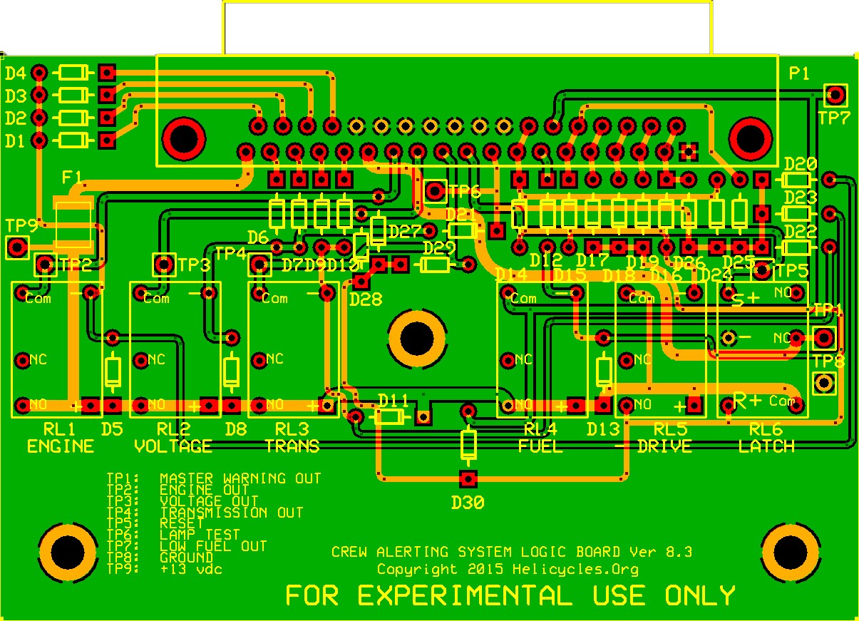
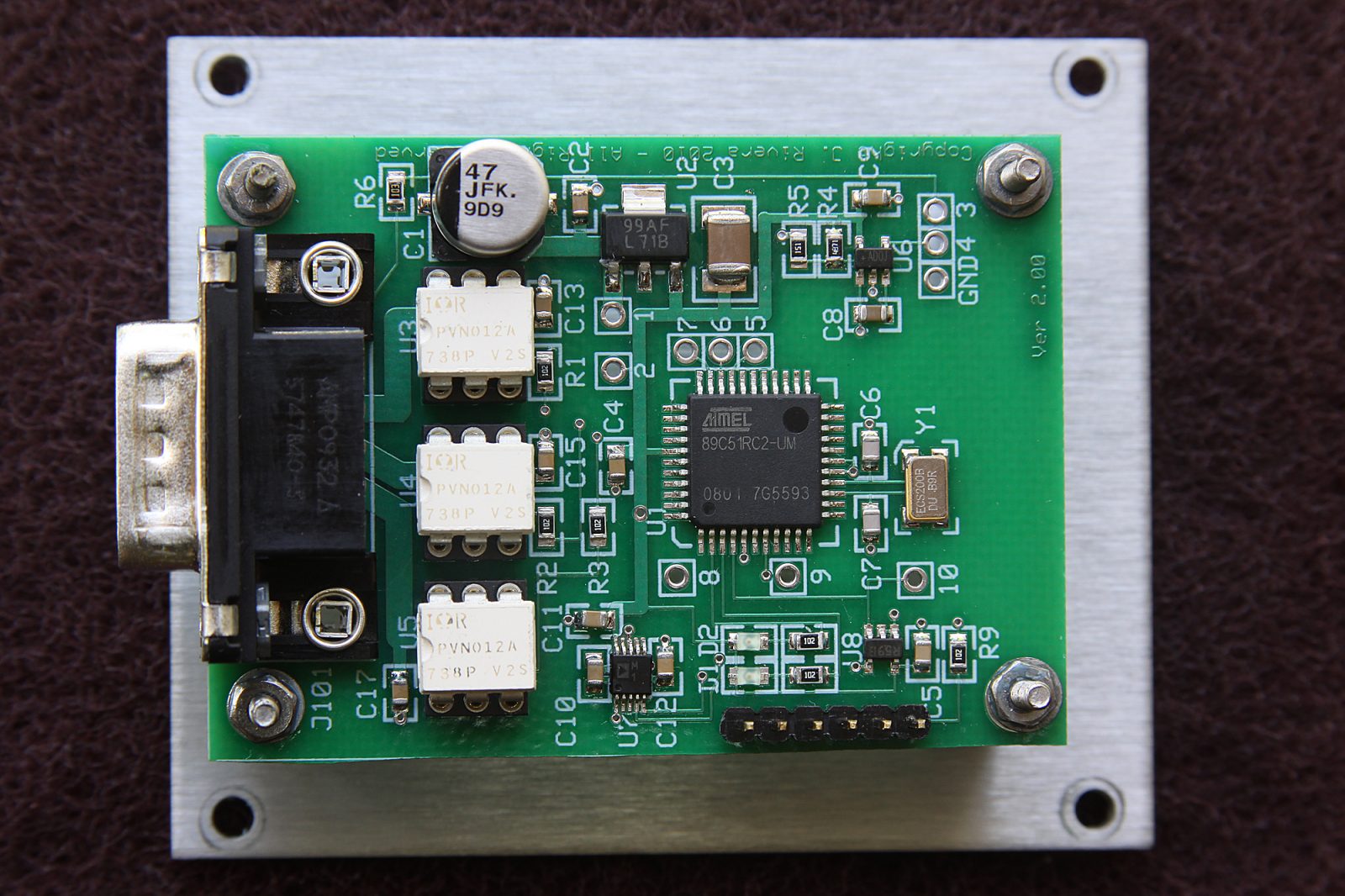
This is the double-sided printed circuit board I designed for the Crew Alerting System (CAS) logic board. Many more hours of project time…
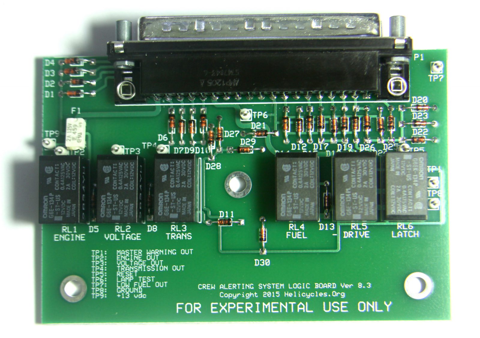
And this is the finished and populated logic board. This CAS board monitored 15 different engine and transmission parameters during flight and would trigger an alert if any of those 15 values strayed out of the normal range. I wish I could have had a chance to fly with my creation…
This is my first generation lower instrument panel. Not much to see except switches and circuit breakers…
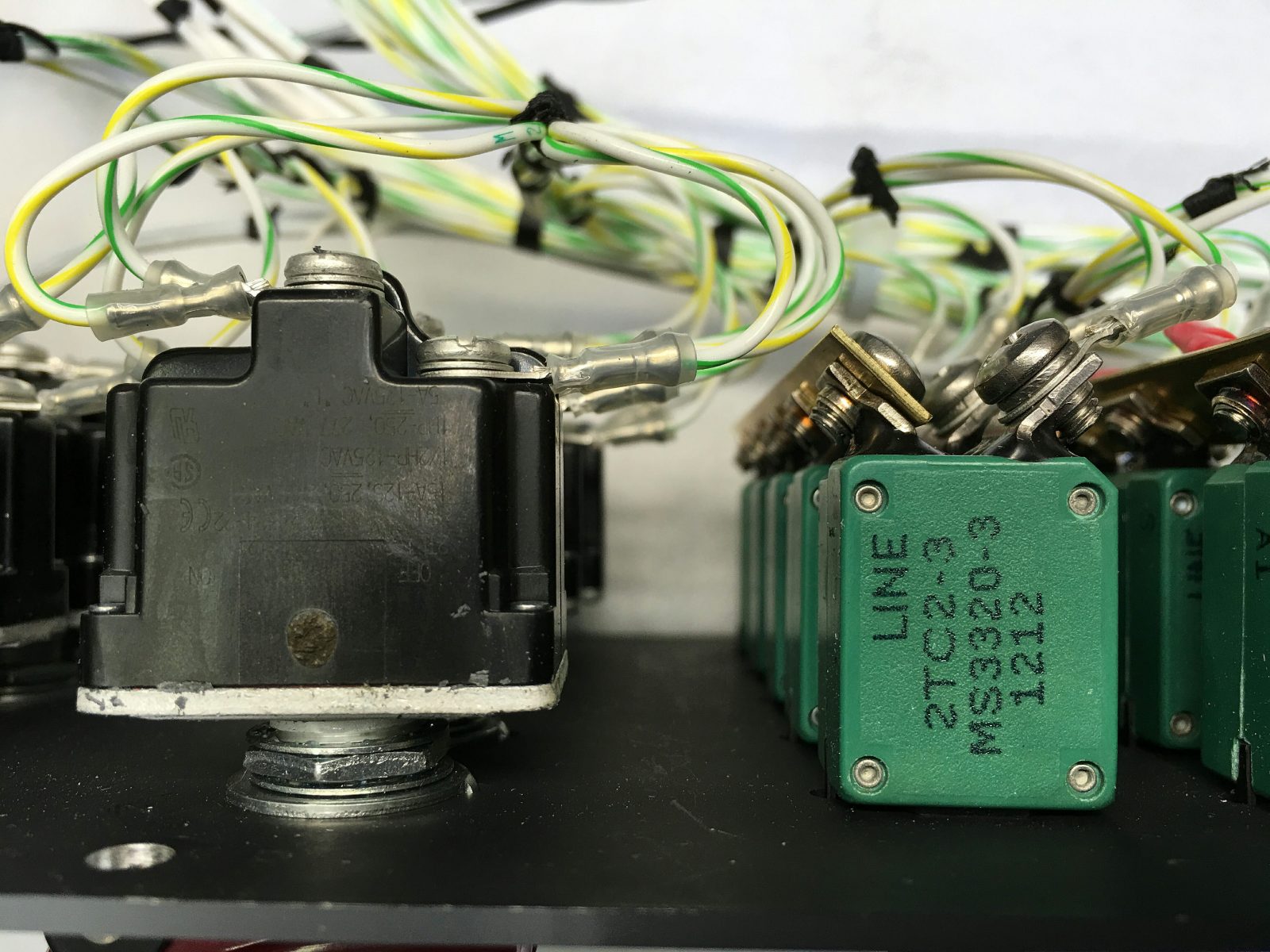
Honeywell sealed aerospace grade toggle switches…
Klixon thermally-compensated aircraft circuit breakers. No auto parts components in my helicopter!
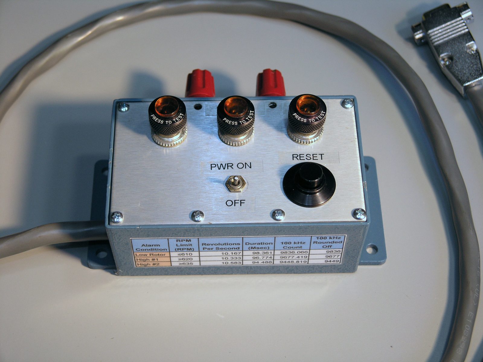
This is my custom Main Rotor RPM Alarm. This was a multi-month project and came out very well. It had three alarm outputs:
Low Rotor: 620 RPM Red Line: > 635 RPM
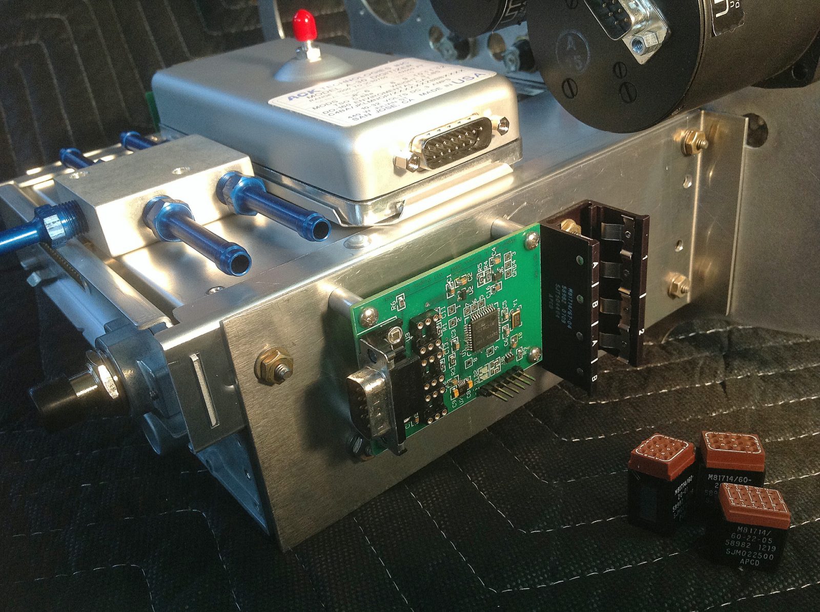
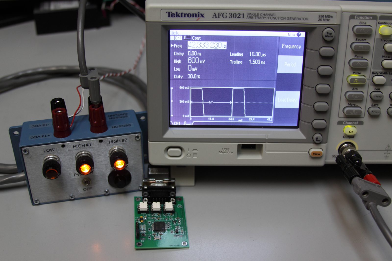
There’s the Rotor Alarm processor board mounted to the side of my avionics shelf…
I spent considerable time and energy testing and validating the Rotor RPM Alarm’s accuracy and reliability. This is my test fixture.
I was able to borrow a very sophisticated arbitrary waveform generator to use while testing. It could precisely duplicate the output waveform of the Hall Effect RPM sensor.
In this picture I am feeding it the equivalent of 635.1 RPM, so both the High Rotor and Red Line alarms are activated…
Another custom enhancement to the basic kit. This one also took months of design work. This is my Interface Chassis which ties all of the subsystems together. The relays are used to handle high-current circuits that exceed the limits of the small switches on the cyclic grip. It’s no wonder it took me three years to finish this project…