LDMOS Amplifier


you need to transmit the strongest signal possible to have any chance of anyone detecting your Moon echos. That requires an antenna with as much gain as possible, and a powerful amplifier. ..
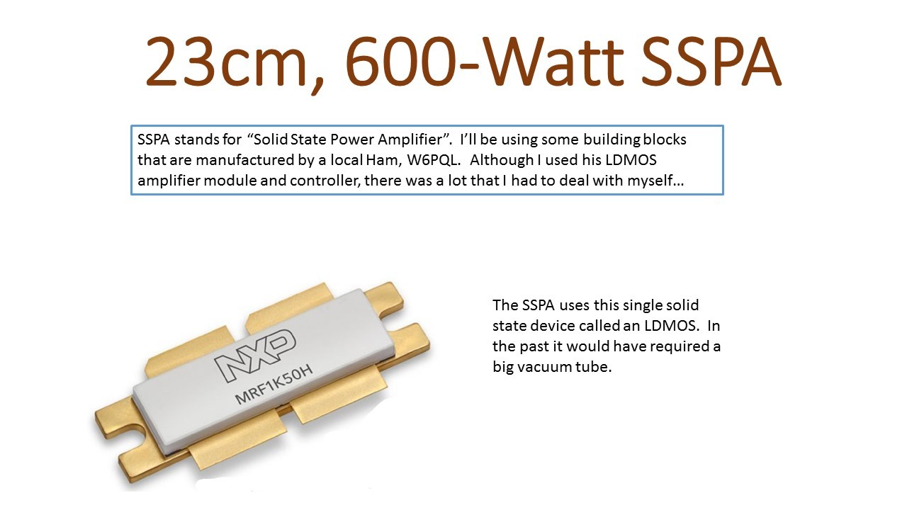
This SSPA is the most powerful Solid State Power Amplifier (SSPA) that I have ever attempted to build, and at the heart of my EME station. This whole undertaking was a huge challenge, and as usual I learned a lot…
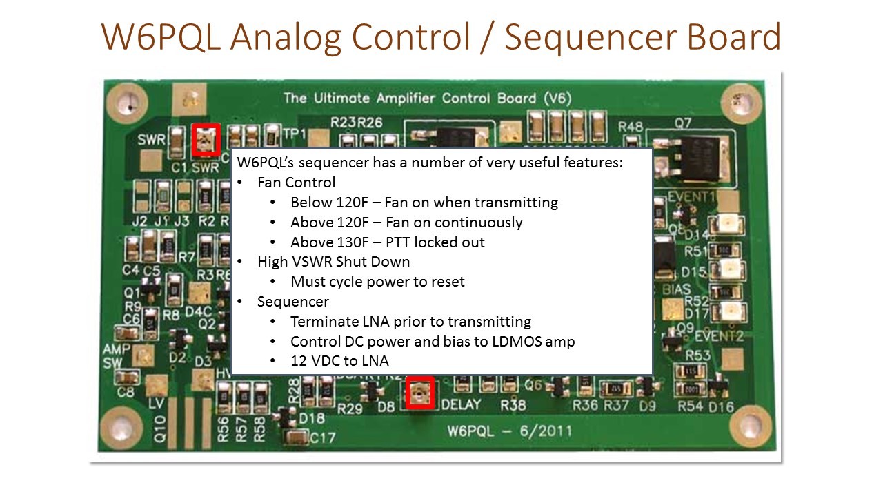
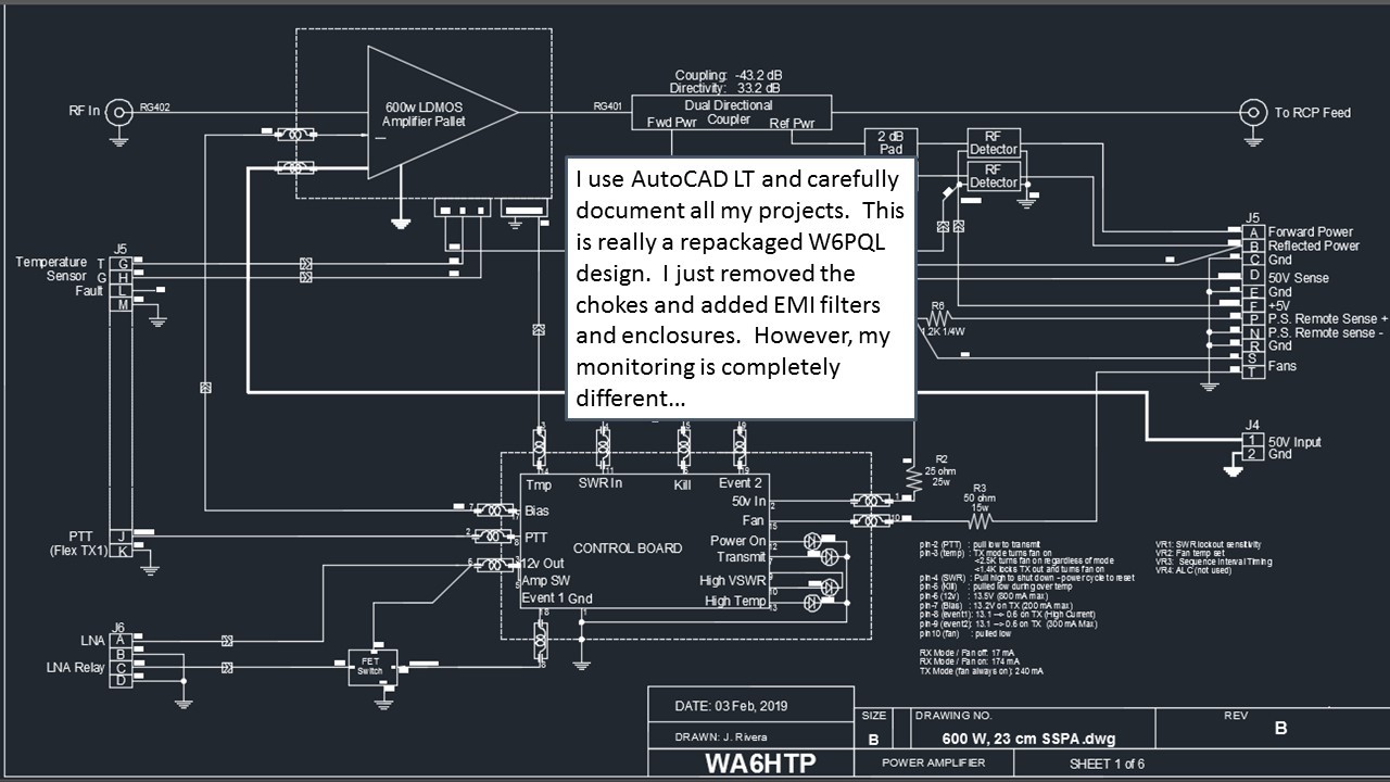
This SSPA is based on components purchased from W6PQL. I am very impressed with his LDMOS amplifier and his Sequencer/Controller, but I wanted to take a different path when dealing with EMI…
Jim clearly had major problems with EMI, judging from the large number of toroids he has scattered around the interior of his enclosure. He also resorted to RF absorbing material to line the inside of the lid. The main cause of his problems is the extremely close proximity between his LDMOS amplifier and sensitive and susceptible circuitry (the Sequencer/Controller).
I believe toroids are Band Aid and not a great solution. I prefer a more systematic approach using shielding and filtering…
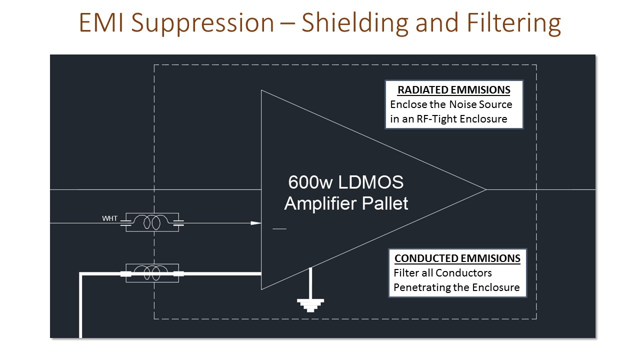
The source of EMI can either be radiated through space, or coupled into signal or power wiring and propagated into susceptible circuitry (Conducted).
We deal with Radiated Emissions by the use of shielding.
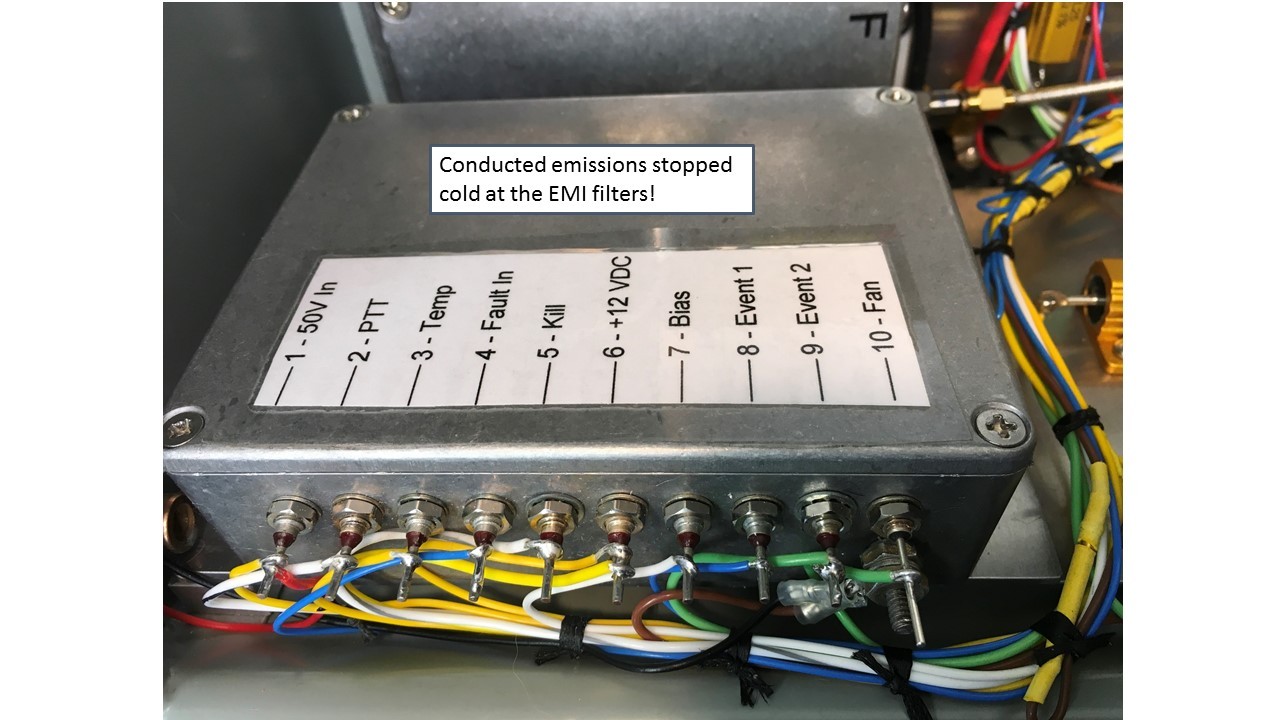
We contain Conducted Emissions inside the shielded enclosure by filtering all wiring that penetrated the shielding.
We protect susceptible circuitry from Radiated Emissions through the use of shielding.
We prevent Conducted Emissions from entering the shielded enclosure through the use of filters.
The concept is quite simple – seal up the bad stuff inside an RF-tight enclosure and trap any conducted EMI through the use of filters. It’s the execution that can be a challenge…
3rd-Order Low Pass
This is a common type of in-line EMI filter that can allow a signal or power conductor to pass through the wall of a shielded enclosure, while trapping conducted EMI.
Look at the specs… It can handle 10-Amps of current at 100 Volts, and attenuation at 1 GHz is 70 dB! That’s going to stop conducted EMI dead!
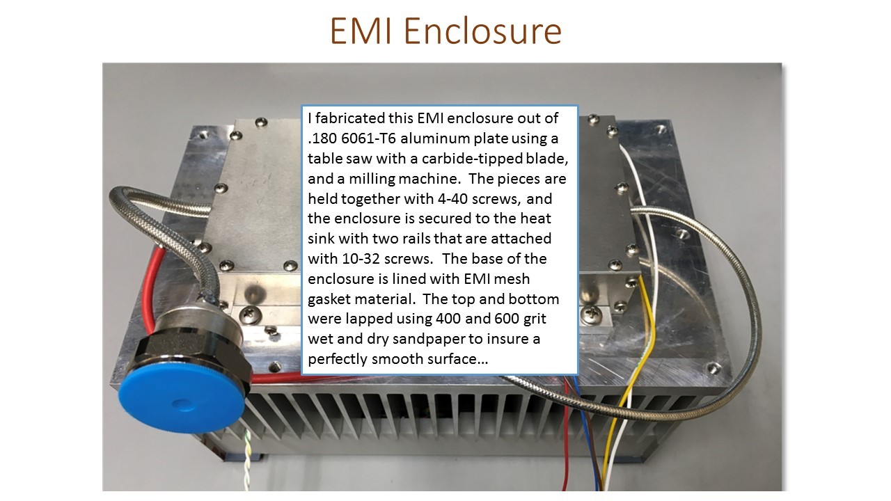
How well my homemade enclosure works will depend entirely on how well I did in eliminating even the smallest gaps.
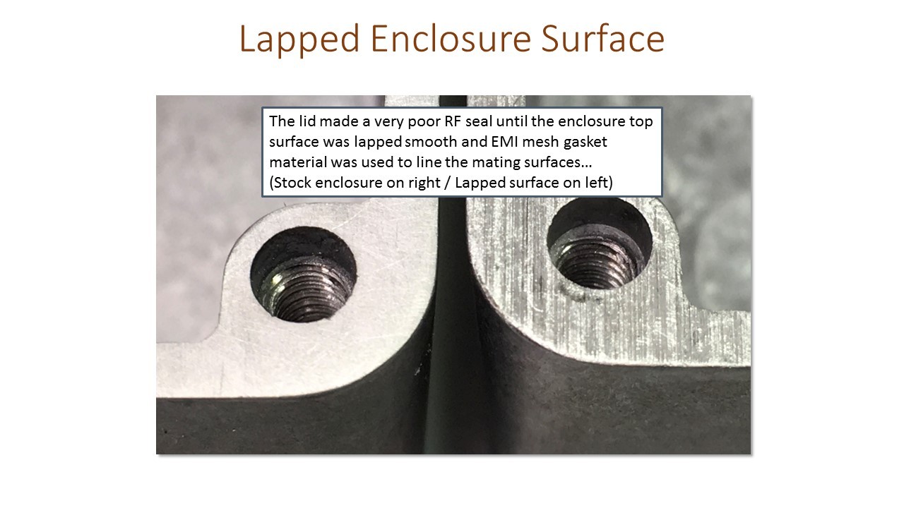
I found out the hard way that even a commercial die-cast aluminum enclosure, with the lid screwed down tight did a horrible job at shielding. It wasn’t until I lapped the enclosure mating surface and added EMI mesh that I achieved a good RF seal…
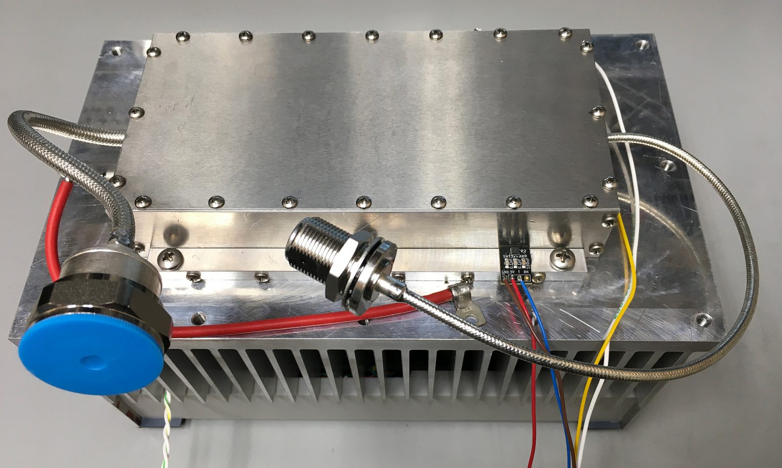
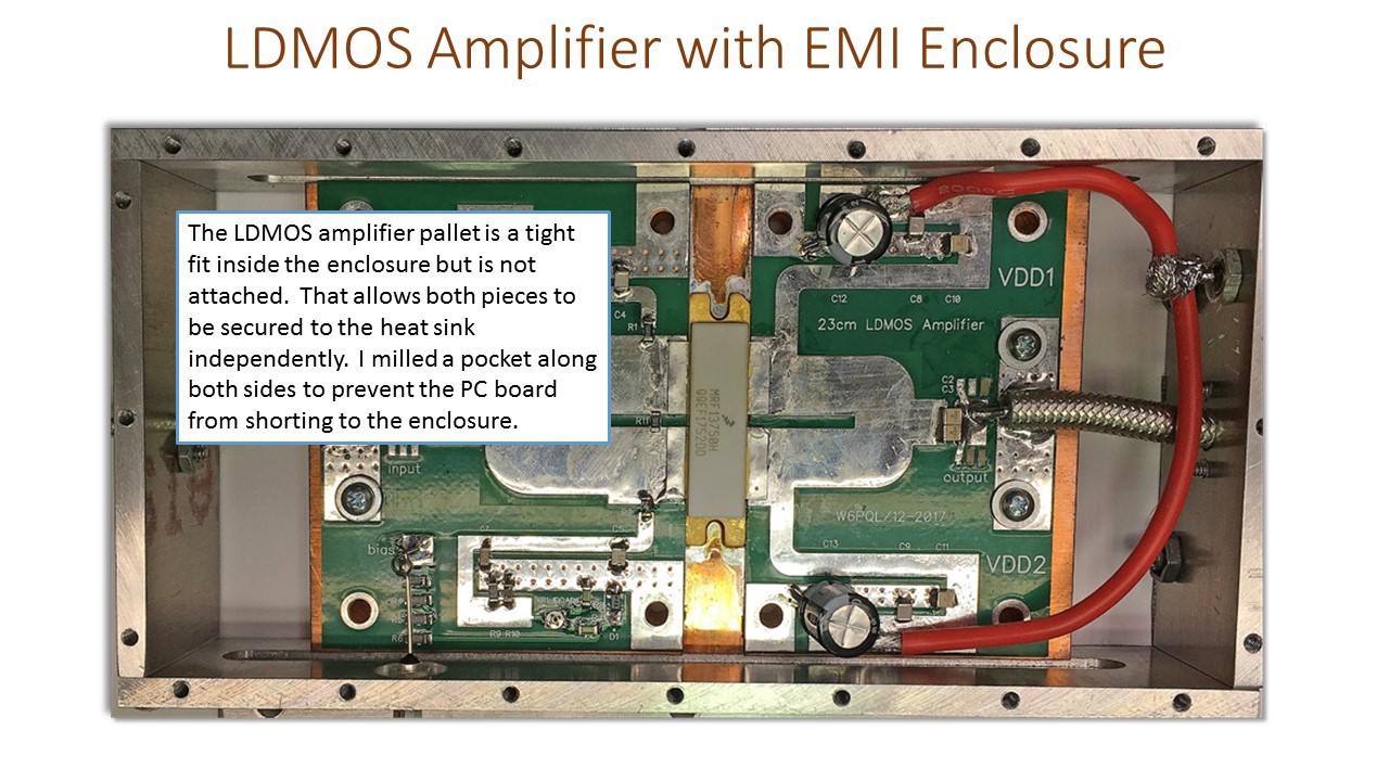
This is the top view, with the lid off. You can see the 30-Amp EMI filter I used for the Vdd +50 Volt lines.
Initially I had planned to use bulkhead feedthrough RF connectors to deal with RF In and Out, but Type-N connectors take up a lot of room and are marginal at this high power level. I ended up simply drilling a clearance hole in the ends of the enclosure and passing the coax through. I’ll show you how that worked in a few slides…
Getting back to the coaxial cables… I made small rectabgular pieces out of .060 copper and drilled the two mounting screw holes as you see, then a small hole where the coax would pass. Using a tapered awl I carefull tapped it into the small hole and enlarged it for a tight fit. That created a tunnel so I had some surface area to solder the coax to. After aligning that piece, I pushes the end away, soldered the coax, then slid the and back and screwed everything together.
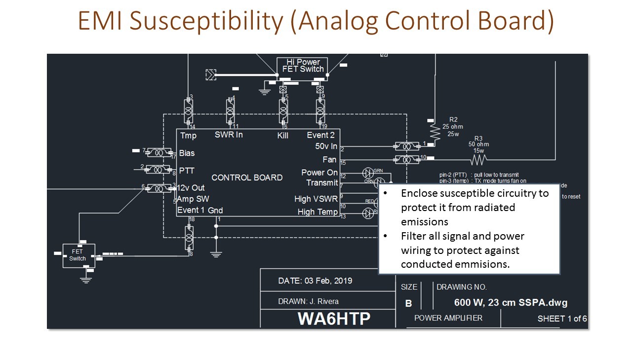
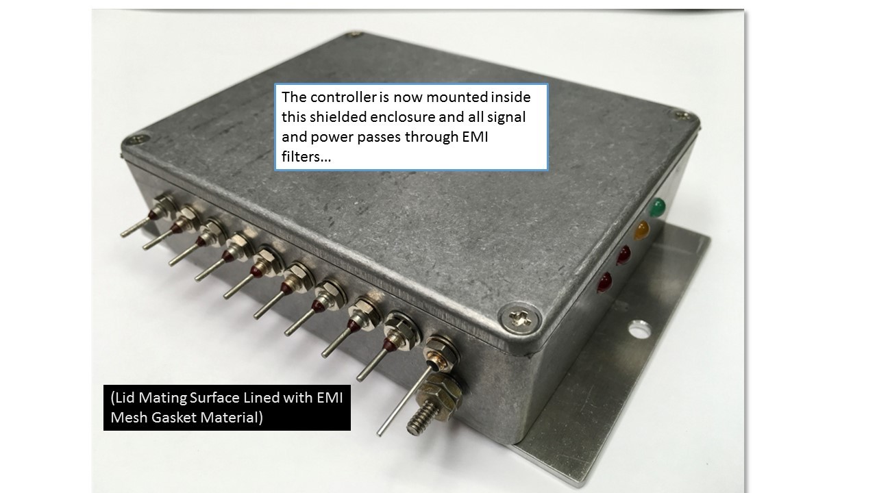
Now I’m dealing with EMI Susceptibility instead of emissions. The only difference is that I’m now trying to keep the interference OUT instead of IN. In my schematic you can see that all signal and power lines pass through EMI filters when penetrating the shielded enclosure
There are a lot of components on this board. That’s why I recommend buying the assembled and tested board and not the kit. It plays nicely with the LDMOS amplifier and the low and high-power FET switches that Jim sells…
You can see that I have lapped the surface of the enclosure so it will make a good RF seal with the lid, once the EMI mesh gasket is installed.
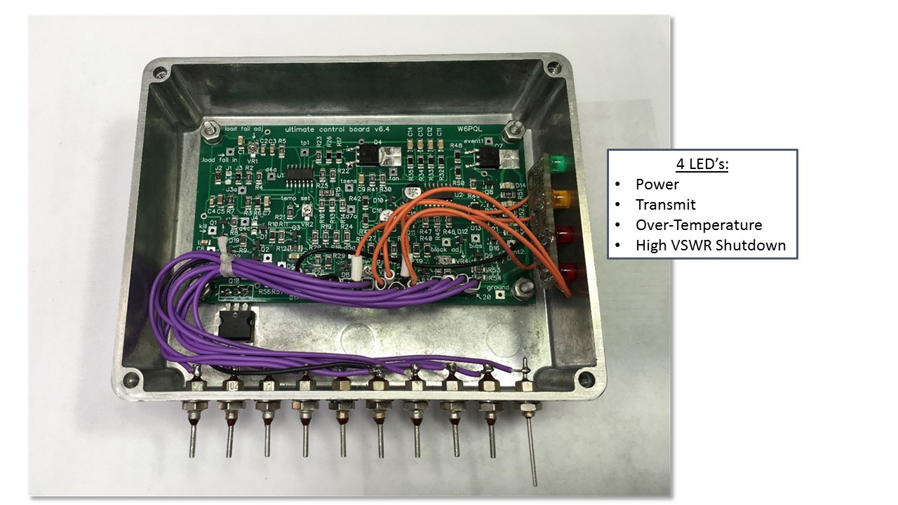
I did violate the shielding rule and I intentionally drilled four small LED clearance holes in the side so I can see the LED’s. It obviously degraded the shielding, but I haven’t experienced any problems…
Here’s the completed Sequencer/Controller, mounted in an almost identical enclosure to the one I used for my high-power directional coupler. Remember that the original coupler performed so poorly that it was useless. It wasn’t until I lapped the top surface of the box and added EMI mesh gasket material to the lid, that it worked properly. I did the same for this enclosure…